
Retractable and rapid disconnect, floating diameter embolic coil product and delivery system

Inactive Publication Date: 2015-11-19
NDI TIP TEKNOLOJILERI ANONIM SIRKETI
View PDF10 Cites 13 Cited by
  • Summary
  • Abstract
  • Description
  • Claims
  • Application Information

AI Technical Summary

Benefits of technology

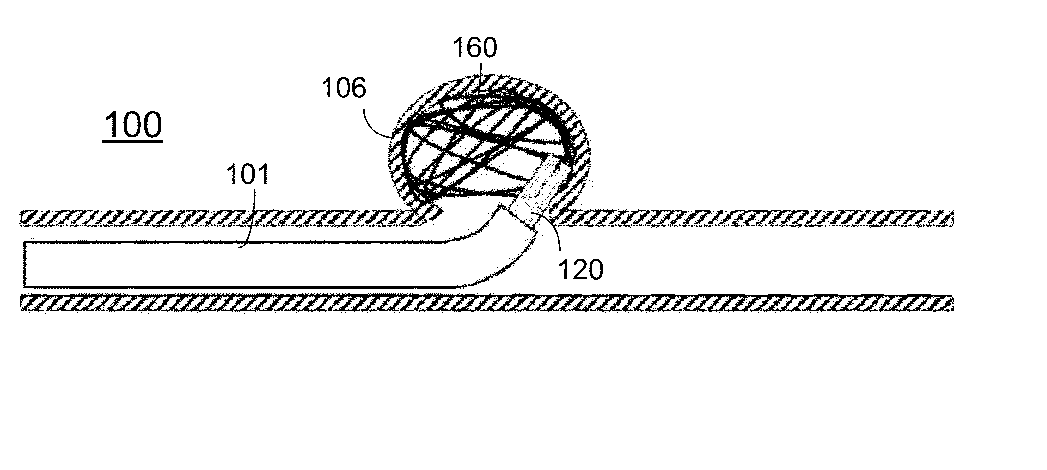
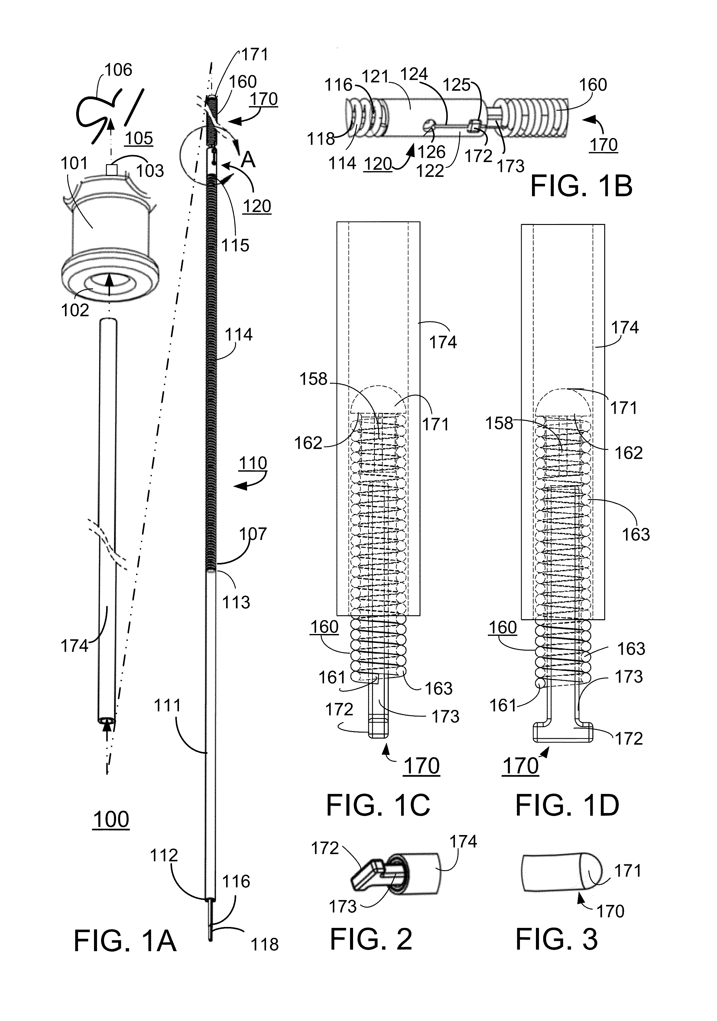
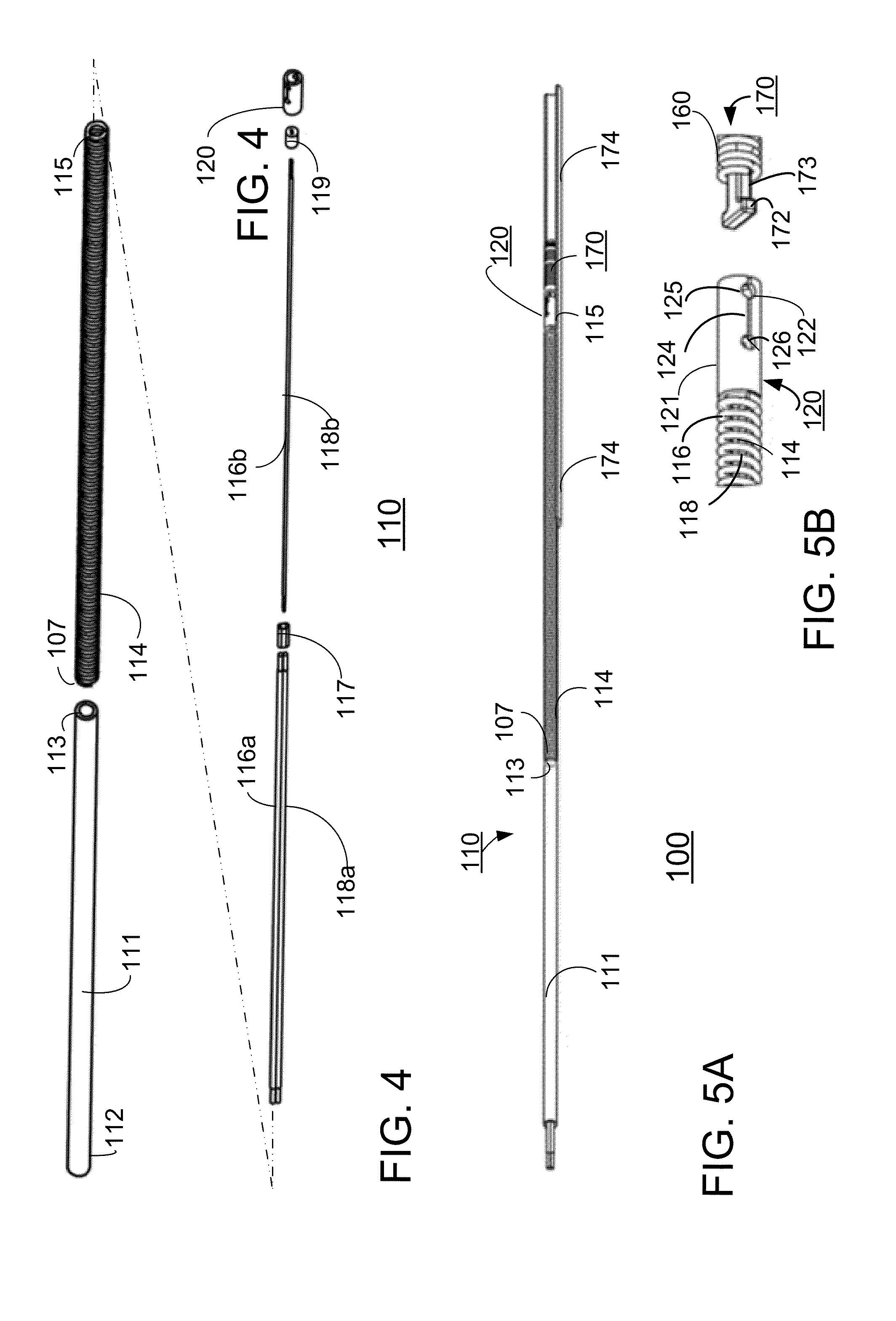
The present invention relates to a vascular device that can be used to treat an aneurysm, which is a ballooning of a blood vessel that can lead to a stroke or other complications. The invention provides an embolic coil that can be easily inserted and detached from a delivery system with a simple push of a button. The embolic coil also has a specific shape that matches the shape of the aneurysm when it is relaxed, thereby improving its efficiency. The invention also includes an improved gripper assembly that can securely hold the embolic coil and deliver it to the desired location in the patient's blood vessel.

Problems solved by technology

Coils are made of metal platinum or stainless steel such that coils are easily seen in radiographic images; however, large coils have a disadvantage in that these can disrupt the radiographic image.
Conventional framework coils may have problems adapting to the shape and / or diameter of the aneurysm sac because the unfolded predetermined three dimensional shape does not conform to the specific shape of the aneurysm sac, which is different each time as the aneurysm sac forms in all different shapes.
Conventional framework coils may form the intended three dimensional shape in an unpredictable fashion and in a less than optimal fit of the aneurysm sac, thereby necessitating multiple coils for an embolization procedure that increase the cost of the embolic procedure.
Conventional three dimensional shapes also are selected at or below the measured diameter of the aneurysm sac, which may result in three dimensional shaped coils not adapting well to the in-between sizes of a measured aneurysm sac.
In this instance, there is an increased risk of complications to the patient should a coil or part of a coil such as an end, become dislodged or fall out of the sac into the venial cavity.
Conventional coils may also lose shape if they are kinked, such as by the operation of the catheter.
Known catheter systems have no way to retract the coil.
If an end or kinked end of the coil, or the entire coil dislodges, from the deployed location there is a significant medical risk that the aneurysm may burst or trigger a clot which then causes distal emboli.
Such a bleed can be life threatening or such emboli may result in neurologic deficit.
Another disadvantage of conventional delivery systems embolic coils and methods used in the embolization procedure is that once a coil is positioned, it is necessary to disconnect the embolic coil from the pusher wire.
A drawback in the art is that conventional mechanical, electrical and chemical disconnect systems are irreversible disconnects.
Mechanical disconnect systems may perform relatively rapidly; however, this required mechanical movement to disconnect has disadvantages as any mechanical movement to free the embolic coil can cause undesirable movement of the placement of the embolic coil such as, for example, leaving a tail of the embolic coil hanging in the lumen of the artery where it can cause turbulence, and other adverse events.
Another disadvantage of conventional mechanical disconnect connections is that once released from the latch, the embolic coil is free and no more control can be exerted over the coil.
Similarly, electrical disconnect connections have disadvantages of coil control, whereby no more control can be exerted on the embolic coil once released and free of the pusher-wire of the catheter.
As discussed, known catheter systems have no way to retract and / or recapture the coil.
If an end of the coil, or the entire coil, dislodges from the deployed location, there is a significant medical risk that the aneurysm may rip or burst, which can be life threatening.

Method used


Image

  • Retractable and rapid disconnect, floating diameter embolic coil product and delivery system
  • Retractable and rapid disconnect, floating diameter embolic coil product and delivery system
  • Retractable and rapid disconnect, floating diameter embolic coil product and delivery system

Examples


Embodiment Construction

[0041]Non-limiting embodiments of the present invention will be described below with reference to the accompanying drawings, wherein like reference numerals represent like elements throughout. While the invention has been described in detail with respect to the preferred embodiments thereof, it will be appreciated that upon reading and understanding of the foregoing, certain variations to the preferred embodiments will become apparent, which variations are nonetheless within the spirit and scope of the invention.

[0042]The terms “a” or “an”, as used herein, are defined as one or as more than one. The term “plurality”, as used herein, is defined as two or as more than two. The term “another”, as used herein, is defined as at least a second or more. The terms “including” and / or “having”, as used herein, are defined as comprising (i.e., open language). The term “coupled”, as used herein, is defined as connected, although not necessarily directly, and not necessarily mechanically.

[0043]R...


PUM


Abstract

A vaso-occlusive device, delivery system and method of delivery to a selected site of the vessel in a manner allowing the vaso-occlusive device to substantially assumes a diameter of an inner surface of the vessel or aneurism sac at the site of the embolization procedure. The vaso-occlusive device or embolic coil has specific properties of wanting to float and conform to the diameter of the aneurysm sac thereby enabling retractability and rapid disconnect detachment for such embolic coil, and a predetermined shape requiring fewer embolic coils per embolization procedure advantageously improving patient risk, and the cost and time of the procedure. A method for deploying the embolic coil with such specific properties to the site of an aneurysm using a delivery system configured for deploying the embolic coil features inserting, and / or reconnecting for positioning and reinserting the embolic coil.

Description

FIELD OF THE INVENTION[0001]The present invention relates to an embolic coil product, delivery system, and method for deploying an embolic coil and, more particularly, an embolic coil with specific properties conforming to a diameter of an aneurysm thereby taking the shape of the aneurysm using a method and delivery assembly that can be used to insert, retract, reconnect, and rapidly disconnect from the embolic coil.BACKGROUND OF THE INVENTION[0002]Conventional mechanical occlusion devices or coils are used for embolization procedures of AVF, aneurysms, or other vascular lesions. These coils can be deployed accurately to a location, e.g. exactly where the catheter ends. In the human brain, different factors such as anatomic anomalies can occur in the arterial blood vessels, thus forming stretched out sacs or aneurysms. Embolization procedures insert coils that may immediately clot the aneurysm sac, thereby stopping the thinner, weaker sidewalls of the arteries from bulging outward f...

Claims


Application Information

Patent Timeline
IPC IPC(8): A61B17/12
CPCA61B17/12145A61B17/12031A61B2017/00867A61B2017/1209A61B2017/1205A61B17/12109A61B17/12113A61B2017/12054A61B2017/12077
Inventor ISLAK, CIVANDEMIRALP, SADIK SEMIHBOYD, GARTH W.KUSKE, MICHAEL J.HABERGER, CAM E.
Owner NDI TIP TEKNOLOJILERI ANONIM SIRKETI
Learn More