Deposition mask production method and laser processing apparatus

a laser processing apparatus and production method technology, applied in the direction of welding/cutting auxillary devices, auxillary welding devices, nuclear engineering, etc., can solve the problems of difficult to uniformly form the opening pattern on the entire mask surface, difficult to form ultrafine opening patterns with favorable accuracy, etc., to reduce the positional deviation of opening patterns and improve the positional accuracy in forming opening patterns

Active Publication Date: 2015-11-19
V TECH CO LTD
View PDF2 Cites 15 Cited by
  • Summary
  • Abstract
  • Description
  • Claims
  • Application Information

AI Technical Summary

Benefits of technology

[0013]According to the present invention, each of the opening patterns is formed over the corresponding preliminary opening pattern in a state in which a part of the internal stress inherent in the resin film is released by forming, in advance, the preliminary opening patterns each having a shape capable of being enclosed in the opening pattern, and thus, it is possible to reduce the positional deviation of the opening patterns after forming the opening patterns. Accordingly, it is possible to improve the positional accuracy in forming the opening patterns by the laser processing.

Problems solved by technology

However, in the conventional deposition mask production method, since the metal plate is subjected to wet etching treatment to form the plurality of opening patterns penetrating the metal plate, it is difficult to form ultrafine opening patterns with favorable accuracy due to the isotropy of the wet etching.
In addition, in a case of a deposition mask for an organic EL display panel, for example, having a large area in which a length of one side is several tens of cm or greater, it is difficult to uniformly form the opening patterns on the entire mask surface due to the occurrence of etching irregularities.

Method used


Image

  • Deposition mask production method and laser processing apparatus
  • Deposition mask production method and laser processing apparatus
  • Deposition mask production method and laser processing apparatus

Examples


Embodiment Construction

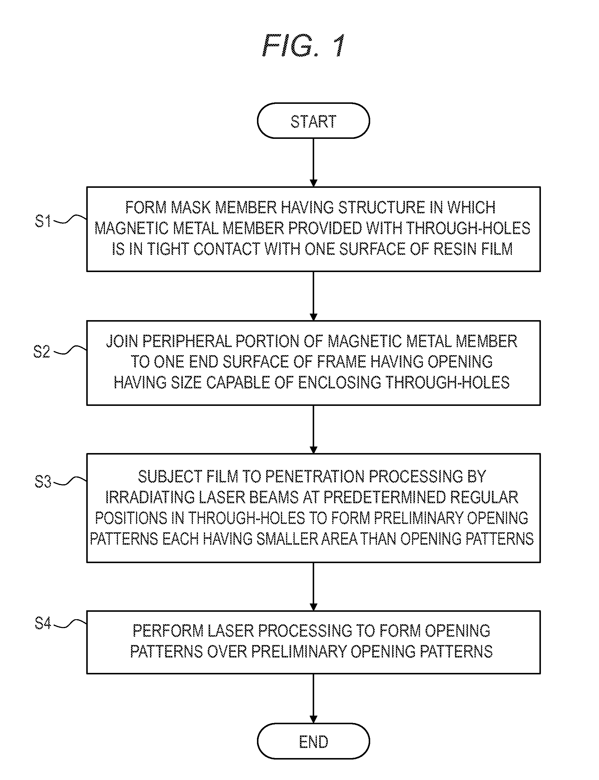
[0025]Hereinafter, an embodiment of the present invention will be described in detail with reference to the accompanying drawings. FIG. 1 is a flowchart illustrating the embodiment of a deposition mask production method according to the present invention. The deposition mask production method is provided to produce a deposition mask having a structure in which a resin film provided with opening patterns is supported by a magnetic metal member having a thin plate shape, and includes step S1 of forming a mask member, step S2 of joining a frame, step S3 of forming a preliminary opening patterns, and step S4 of forming the opening patterns.

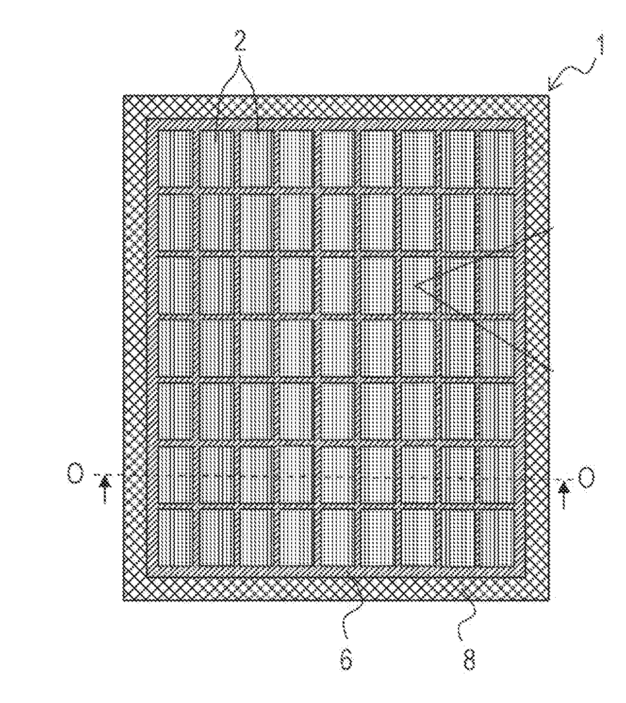
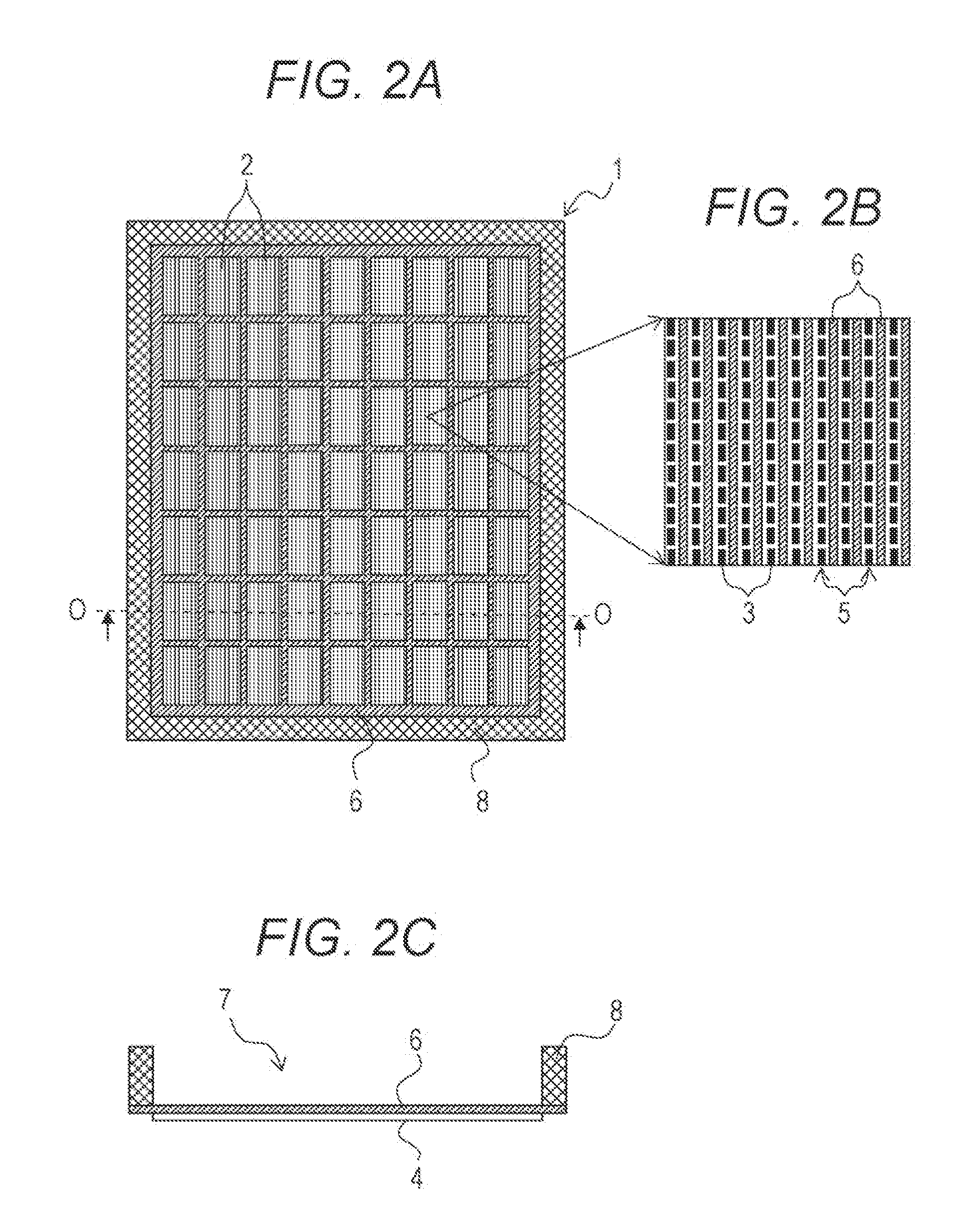
[0026]Here, as illustrated in FIGS. 2A to 2C, a description will be made regarding a production method of a deposition mask 1, for example, as a deposition mask 1 having a large area corresponding to a substrate having a large area and attached with a plurality of, for example, organic EL panels, and the deposition mask 1 in which a plurality of unit ...


PUM

PropertyMeasurementUnit
thicknessaaaaaaaaaa
thicknessaaaaaaaaaa
temperatureaaaaaaaaaa

Abstract

A method including: a first step of forming a mask member having a structure in which a magnetic metal member provided with through-holes is in tight contact with one surface of a film; a second step of forming a plurality of preliminary opening patterns by subjecting the film to penetration processing by irradiating laser beams at predetermined regular positions in the plurality of through-holes; and a third step of performing laser processing so as to form each opening pattern over the corresponding preliminary opening pattern, is provided.

Description

CROSS-REFERENCE TO RELATED APPLICATION[0001]This application is a continuation application of International Application No. PCT / JP2013 / 084811, filed on Dec. 26, 2013, which is hereby incorporated by reference in its entirety for all purposes.BACKGROUND OF THE INVENTION[0002]1. Field of the Invention[0003]The present invention relates to a production method of a deposition mask having a structure in which a resin film provided with opening patterns is supported by a magnetic metal member having a thin plate shape, and in particular, relates to a deposition mask production method and a laser processing apparatus, capable of improving positional accuracy in forming opening patterns by laser processing.[0004]2. Description of Related Art[0005]According to a conventional deposition mask production method, a first resist pattern having a plurality of through-holes is formed on a metal plate, and a plurality of penetrating opening patterns is formed in the metal plate by performing an etch...

Claims


Application Information

Patent Timeline
Patent Type & Authority Applications(United States)
IPC IPC(8): B05D3/06B05D1/02
CPCB05D1/02B05D3/06C23C14/04B23K37/0235B23K37/0408B23K26/08B23K26/40B23K26/382B23K26/066B23K2101/40
Inventor MIZUMURA, MICHINOBU
Owner V TECH CO LTD
Why Eureka
Try Eureka