
Device designed to receive a biological sample

a biological sample and device technology, applied in the field of biological sample analysis and/or transfer, can solve the problems of affecting the safety of technicians who handle biological samples, and the way in which people who handle these blood bags may come into contact with the sample, so as to avoid the risk of contamination of the environment and ensure the operation of the device.

Active Publication Date: 2015-11-19
BIOMERIEUX SA
View PDF0 Cites 9 Cited by
  • Summary
  • Abstract
  • Description
  • Claims
  • Application Information

AI Technical Summary

Benefits of technology

The invention is about a device for collecting biological samples, like stool samples, which is easier and more comfortable to use. The device has a hollow tube-shaped tubing attached to a container, with a flared open end to make it easier to collect samples. In its first position, the device has a special shape that matches the inside of a glove, allowing for easy adjustment and positioning of biological and physicochemical information capture means for analysis of the sample. This makes it easier to collect samples that are not perfectly homogenized or are in semi-solid form. The device provides a better and more convenient way to collect biological samples for analysis.

Problems solved by technology

In the field of analysis, particularly that of biological analysis (and more particularly of microbiological analysis), the problem is regularly posed of the safety of technicians who handle biological samples, particularly due to the risks of contamination that exist when an aliquot is taken for purposes of analysis.
Blood bags, due to their flexible walls, are containers far from being easy to handle.
It follows that people who handle these blood bags may very easily come into contact with the sample and risk being contaminated if the bags are not pathogen-free.
For instance, it happens that, during the sampling of biological liquids, such as urine, suspected of being contaminated, the personnel who take the samples contaminate the samples themselves, making it impossible to provide a reliable diagnosis from said samples.
Furthermore, such handling conditions substantially increase analysis time.
Thus, productivity may be severely impeded when the number of samples is large.

Method used


Image

  • Device designed to receive a biological sample
  • Device designed to receive a biological sample
  • Device designed to receive a biological sample

Examples


first embodiment

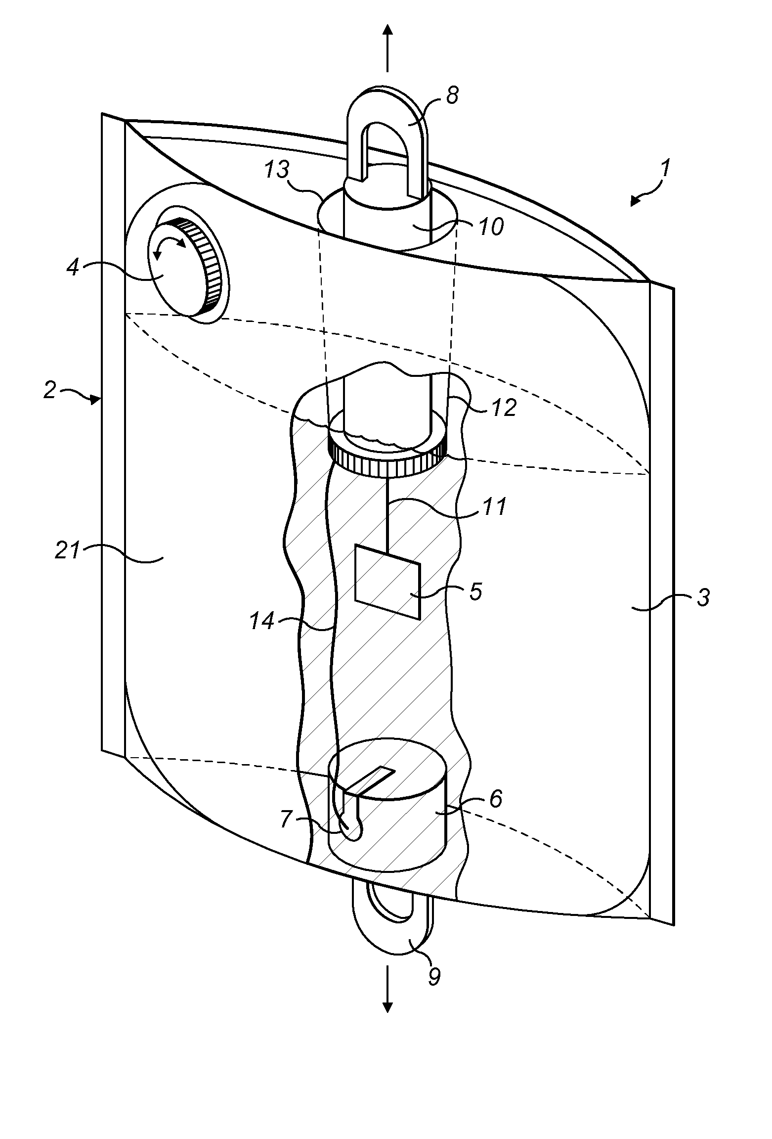
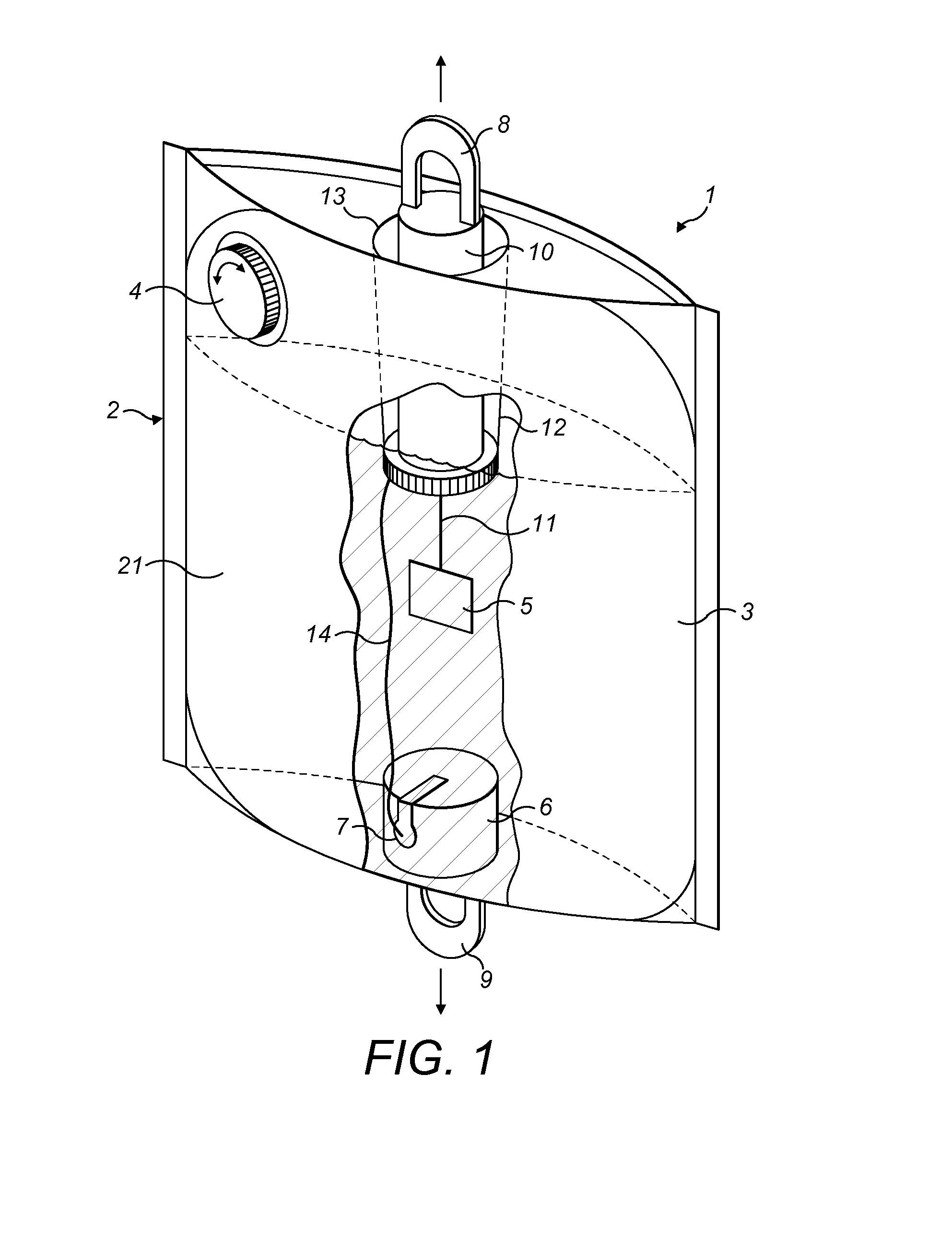
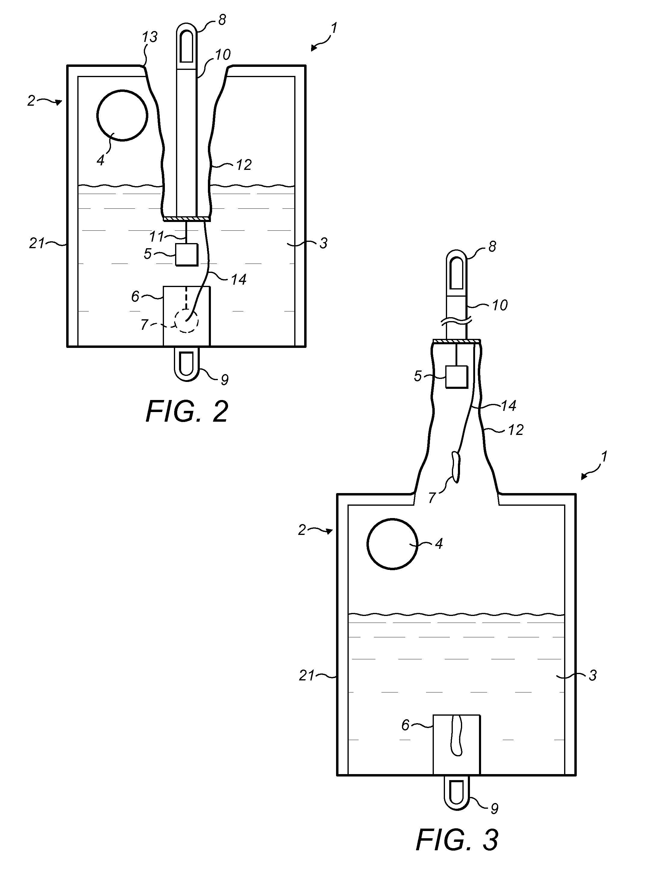
[0239]FIG. 1 shows the device 1 according to the present invention. The device 1 comprises a container 2 in bag form designed to incubate a biological sample. The container 2 comprises, for example, rigid paper, paperboard, polyethylene, polyvinyl chloride, polypropylene, polystyrene, polyethylene terephthalate, and any suitable combination of these materials and / or any other material (preferably bio-based materials) such that the container 2 has sufficient physical characteristics, particularly in terms of behaviour and sufficient sealing of the container 2. In order to carry out the incubation of said sample, a culture medium 3, such as enrichment broth, is introduced into the container 2. The container 2 is equipped with an opening able to shift from an “open” position to a “closed” position by means of a cap 4. When the cap 4 is removed, the opening may allow the introduction into the container 2 of a biological sample. After the introduction of said biological sample, the cap 4...

second embodiment

[0259]FIG. 6 shows the device 1 according to the invention. The device 1′ as shown in FIG. 6 comprises a shank-shaped sampling means 50 comprising a spongy means, such as cotton, said spongy means having the ability to absorb at least a certain amount of biological material diluted in culture medium 3′, such as enrichment broth, present inside the container 2′.

[0260]Unlike the sampling means 5 shown in FIG. 1, the sampling means 50 is not designed to specifically capture and detect target microorganisms by visual or optical analysis, for example. On the other hand, this sampling means 50 is designed to absorb a certain amount of biological material and to transfer it inside the wall 12′ when the device 1′ is shifted from its first position, as shown in FIG. 6, to its second position (release / transfer position, not shown), in a manner similar to the operation shown in FIGS. 2 and 3 and described with reference to said figures.

[0261]As described in reference to FIGS. 4, 4a and 4b, the...

third embodiment

[0262]FIG. 7 shows the device 100 according to the invention. The device 100 comprises a container 102 designed to receive therein culture medium 103, such as enrichment broth. Moreover, a sampling means 105 is present inside the container 102. The device 100 comprises an opening hermetically sealed by means of a cap 104. When the cap 104 is removed, a biological sample may be introduced into the container 102. The sampling means 105 is designed to detect and capture a target bacterium inside the container 102. The sampling means 105 is also designed for visual or optical analysis. The device 100 as shown in FIG. 7 comprises a container 102 equipped with partially transparent walls. That means that the visual or optical analysis of the sampling means 105 is possible through the walls of the container 102.

[0263]In order to force on an operator a specific use of the device 100 as shown in FIG. 7, the device 100 comprises a mask 140 (representing an analysis restricting means in the se...


PUM


Abstract

Device designed to receive at least one biological sample, said device comprising:at least one container,at least one sampling means positioned inside the enclosure of said container,at least one container, such as a pouch or a compartment, comprising at least one disinfecting agent,optionally at least one analysis restricting means,wherein at least a portion of said sampling means and / or at least a portion of the analysis restricting means are / is designed to shift from a first position to a second position, andwherein said portion of said sampling means and / or said portion of the analysis restricting means are / is connected to said receptacle such that the opening of said receptacle can be mechanically induced by shifting from said first position to said second position.

Description

TECHNICAL FIELD[0001]The present invention relates generally to the analysis and / or transfer of biological samples for purposes of analysis. Generally, the present invention aims at reducing the risks of contamination of the environment and / or of personnel within the context of analyses—and more generally of handling—of biological samples, preferably those likely / suspected to contain microbiological material.STATE OF THE ART[0002]In the field of analysis, particularly that of biological analysis (and more particularly of microbiological analysis), the problem is regularly posed of the safety of technicians who handle biological samples, particularly due to the risks of contamination that exist when an aliquot is taken for purposes of analysis. This is particularly true when analysis devices are used, for example to detect one or more target microorganisms, outside the laboratory within the context of “point-of-care” technologies.[0003]Thus are known the risks taken by technicians re...

Claims


Application Information

Patent Timeline
IPC IPC(8): C12Q1/04G01N21/78G01N31/22
CPCC12Q1/04G01N21/78G01N31/226B01L3/502B01L3/505B01L3/523B01L2200/141B01L2300/047B01L2300/049B01L2300/0618B01L2300/069B01L2300/0819B01L2400/0683
Inventor COLIN, BRUNOMONTET, MARIE-PIERREROZAND, CHRISTINE
Owner BIOMERIEUX SA
Learn More