Expandable Boundary Layer Turbine

a technology of boundary layer turbines and turbine blades, which is applied in the direction of machines/engines, manufacturing tools, mechanical equipment, etc., can solve the problems of increasing maintenance costs and dependability, not gaining widespread application, and the blades of conventional turbines are expensive to construct, so as to reduce the risk of distortion and breakage, improve the support of the disk, and minimize the disturbance of the natural flow of fluids.

Inactive Publication Date: 2015-11-19
THRUSTCYCLE ENTERPRISES
View PDF2 Cites 7 Cited by
  • Summary
  • Abstract
  • Description
  • Claims
  • Application Information

AI Technical Summary

Benefits of technology

[0007]This invention provides a method to construct a boundary layer turbine that is much cheaper to construct and maintain than conventional turbines because it uses flat disks that can be precision cut at low cost. The design of this invention is an improvement over previous boundary layer turbines because the bolt-on hub design significantly decreases breakage and distortion. Delta-wing shaped center spacers and teardrop shaped outer spacers further increases durability by providing improved support for the disks while minimizing the disturbance of the natural flow of fluids. The use of endplates with heavy outer rims results in turbines with greater gyroscopic effect and greater mass for kinetic energy storage. The focused inlet nozzle system increases efficiency by directing flows to the individual disks. Coating the inner case of the turbine's enclosure with Teflon or similar materials will reduce friction and further improve efficiency.
[0009]By bolting on hubs directly to disks and not putting a hole through the middle of them, this invention is much stronger and less susceptible to distortions and breakage. Furthermore the delta wing shaped center spacers and teardrop shaped outer spacers in this invention improve support for the disks while minimizing the disturbance of the natural flow of fluids. The use of endplates with heavy outer rims results in turbines with greater gyroscopic effects and greater mass for kinetic energy return. The tuned inlet nozzle system within the containment case with directed streams going to each individual disk increases the efficiency of the system. Coating the inner case of the turbine's enclosure with Teflon or similar materials will reduce friction and further improve efficiency.
[0010]The present invention differs from existing prior art because of its simple design. The expandable turbine is much cheaper to build and maintain than a conventional turbine, while also being less fragile.
[0011]The present invention provides a method to construct a boundary layer turbine that is much cheaper to construct and maintain than conventional turbines because it uses flat disks that can be precision cut at low cost. The design of this invention is an improvement over previous boundary layer turbines because the bolt-on hub design significantly decreases breakage and distortion. Delta wing shaped center spacers and teardrop shaped outer spacers provide improved support for the disks while minimizing the disturbance of the natural flow of fluids. The use of endplates with heavy outer rims results in turbines with greater gyroscopic effects and greater mass for kinetic energy storage. The directed-flow tuned inlet nozzle system further increases efficiency. Coating the inner case of the turbine's enclosure with Teflon or similar materials will reduce friction and further improve efficiency.

Problems solved by technology

As stated above, conventional turbine blades are expensive to construct because of their complexity and level of detail.
The complexity also adds to fragility and the exposed blades make them prone to breakage, increasing maintenance cost and decreasing dependability.
Nikola Tesla turbine's employed a simpler design but did not gain widespread application at the time of its invention in part due to limitations of metallurgical technology.
Subsequent attempts by experimenters have failed to produce a turbine of significant capacity and durability because they follow the original concept with a large hole through the center, thereby weakening the structure and leaving the disks susceptible to distortion and breakage.
Recent experiments have been limited to smaller boundary layer turbines with limited water or air pressure applied.

Method used


Image

  • Expandable Boundary Layer Turbine
  • Expandable Boundary Layer Turbine
  • Expandable Boundary Layer Turbine

Examples


Embodiment Construction

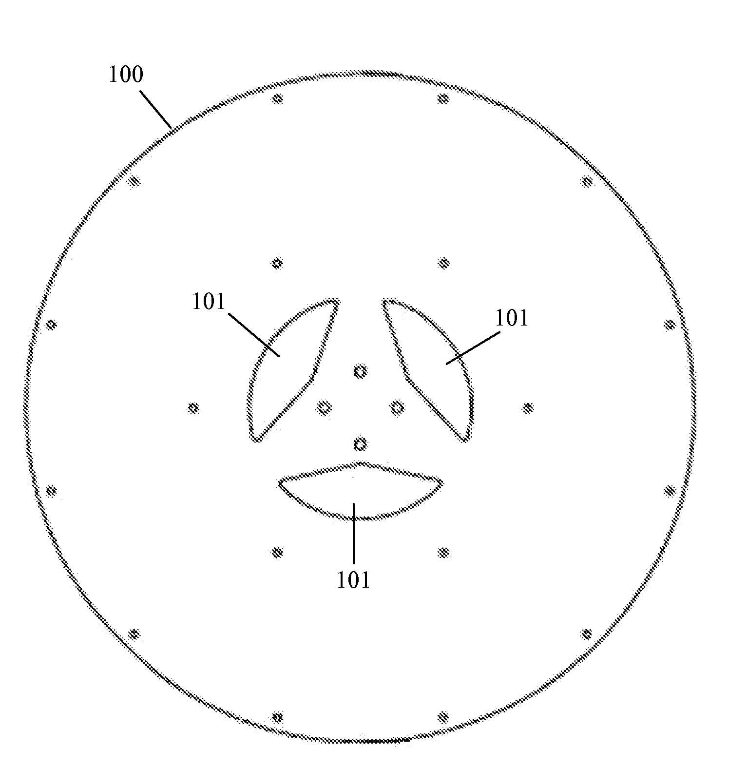
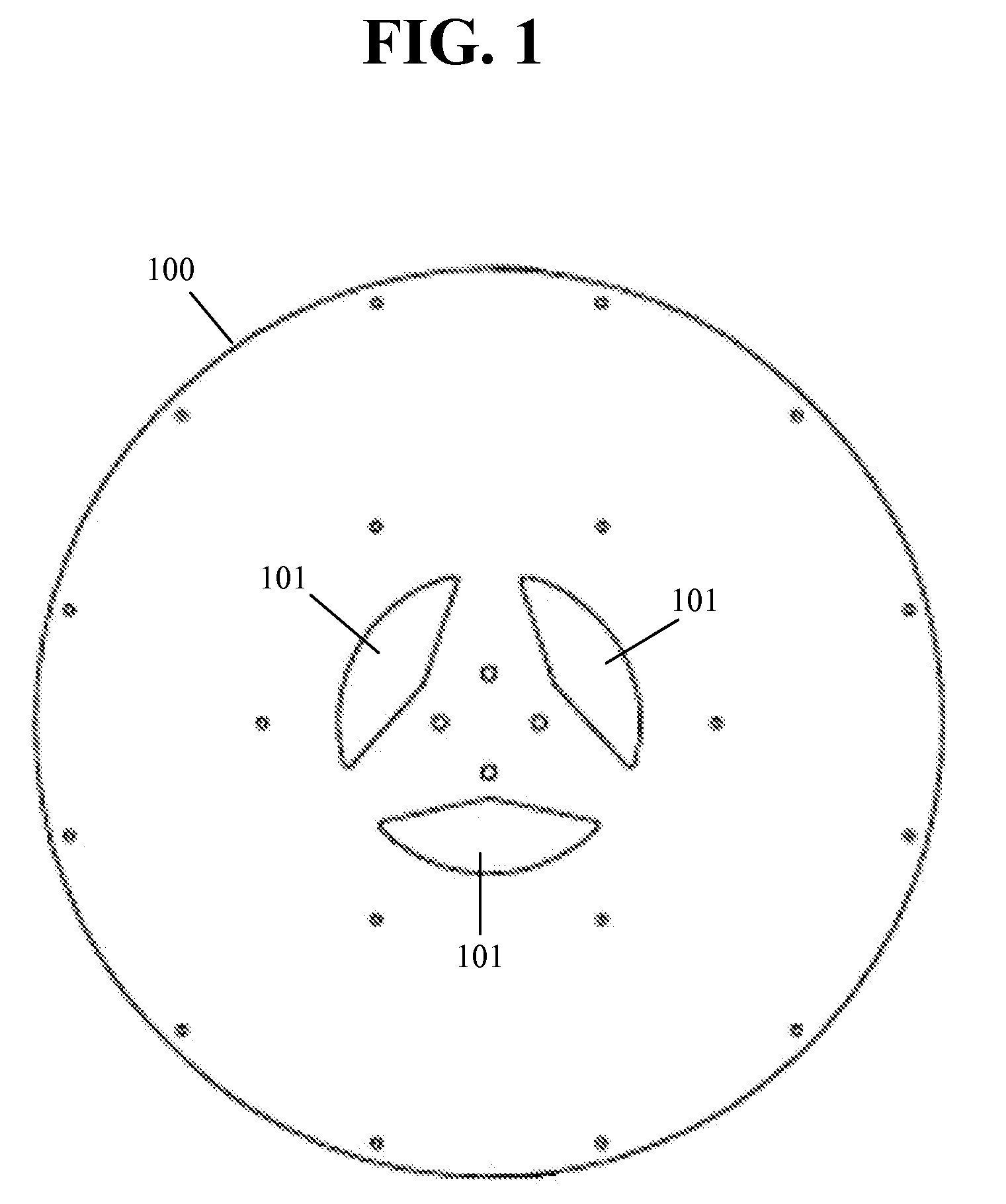
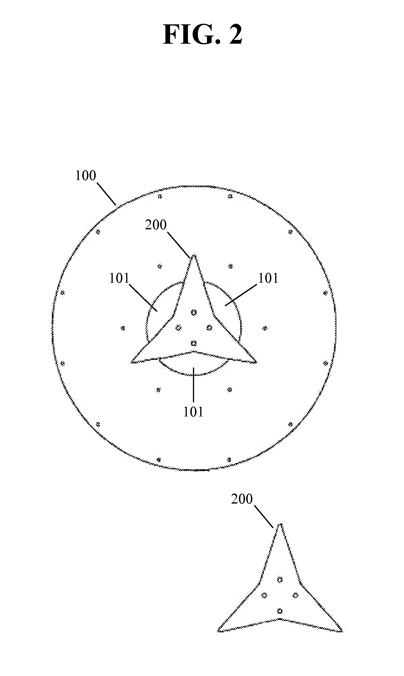
[0024]The present invention pertains to a low-cost boundary layer turbine comprising a bolt-on hub and directed-flow tuned inlet nozzle design that significantly decreases breakage and distortion and increases the efficiency of the system. The following description contains specific information pertaining to various embodiments and implementations of the invention. Furthermore, the present specification need not represent some of the specific details of the present invention in order to not obscure the invention. A person of ordinary skill in the art would have knowledge of such specific details not described in the present specification. Others may omit or only partially implement some features of the present invention and remain well within the scope and spirit of the present invention.

[0025]The following drawings and their accompanying detailed description apply as merely exemplary and not restrictive embodiments of the invention. To maintain brevity, the present specification ha...


PUM

PropertyMeasurementUnit
cohesionaaaaaaaaaa
durabilityaaaaaaaaaa
lengthaaaaaaaaaa

Abstract

A boundary layer turbine that uses flat disks that can be precision cut at low cost is more cost-effective to construct and maintain than conventional turbines. Bolt-on hub design significantly decreases breakage and distortion. Delta-wing shaped center spacers and flow enhancing, teardrop-shaped outer spacers further increase durability by providing improved support for the disks while minimizing the disturbance of the natural flow of fluids. Use of endplates with heavy outer rims results in turbines with greater gyroscopic effect and greater mass for kinetic energy storage. A disk-directed inlet valve and focused inlet nozzle system increases efficiency by directing flows to the individual disks valve in a low friction containment case. The directed flow tuned inlet nozzle system further increases efficiency. Coating the inner case of the turbine's enclosure with Teflon or similar materials reduces friction and further improves efficiency.

Description

CROSS-REFERENCE TO RELATED APPLICATIONS[0001]This application claims priority to and the benefit of U.S. Provisional Patent Application Ser. No. 61 / 824,829 filed on May 17, 2013 by David Allan Ryker and Clyde Igarashi, entitled Expandable Boundary Layer Turbine With Bolt-on Hubs, Center Support Spacers, Directed Stream Inlet Valve, and Gyro Endplates; which is hereby incorporated herein by reference in its entirety.BACKGROUND OF THE INVENTION[0002]1. Field of the Invention[0003]The present invention is generally in the field of boundary layer turbines. More specifically, the present invention teaches a low-cost boundary layer turbine comprising a bolt-on hub and directed-flow tuned inlet nozzle design that significantly decreases breakage and distortion and increases the efficiency of the system.[0004]2. Background Art[0005]Conventional turbine blades are expensive to construct because of their complexity and level of detail. The complexity also adds to fragility and the exposed bla...

Claims


Application Information

Patent Timeline
Patent Type & Authority Applications(United States)
IPC IPC(8): F01D5/30F01D25/00F01D1/18
CPCF01D5/3069Y10T29/49323F01D25/005F01D1/18F01D1/36
Inventor RYKER, DAVID ALLANIGARASHI, CLYDE
Owner THRUSTCYCLE ENTERPRISES
Why Eureka
Try Eureka