
Fuel treatment apparatus

Inactive Publication Date: 2015-11-26
ZHANG CHI +5
View PDF3 Cites 3 Cited by
  • Summary
  • Abstract
  • Description
  • Claims
  • Application Information

AI Technical Summary

Benefits of technology

The patent describes an apparatus that uses magnetic field and ultraviolet light to break up fuel molecules and improve fuel quality. The apparatus can reduce impurities and generate inorganic salts that decrease negative burning products from combustion. The treated fuel shows better antiknock performance, higher energy output, and reduced engine noise. It can also protect engines from poor quality fuel oil. The apparatus can be used in engines and help with carbon deposition and coke dissolution. A time-varying magnetic field generated by an electromagnetic coil is believed to enhance fuel treatment. Overall, the patent describes an effective apparatus for fuel treatment to create better fuel quality and protect engines.

Problems solved by technology

The fuel processed by the apparatus may also dampen engine noise and undermine modular stability of poor quality fuel oil.

Method used


Image

  • Fuel treatment apparatus
  • Fuel treatment apparatus
  • Fuel treatment apparatus

Examples


third embodiment

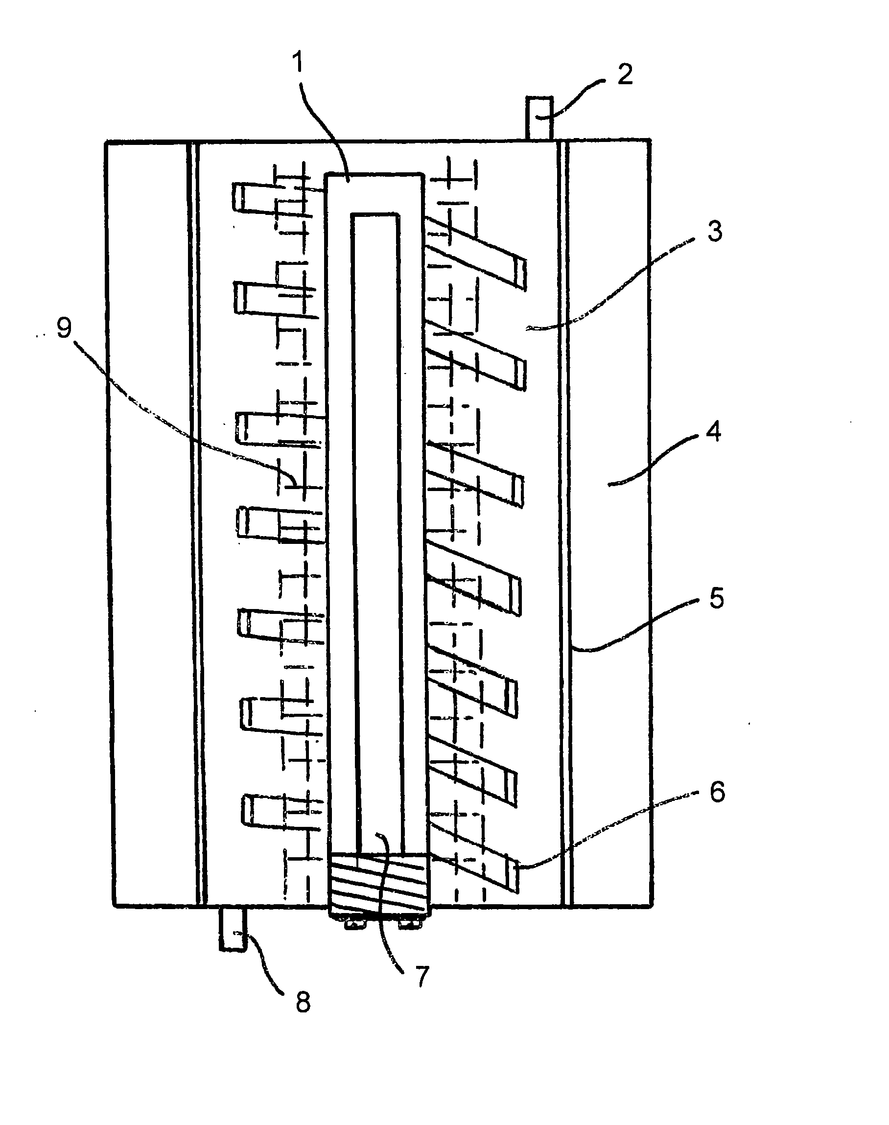
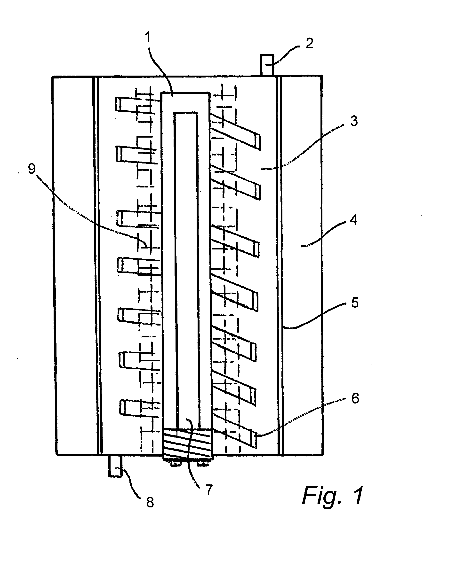
[0073]apparatus in accordance with the invention will now be described with reference to FIGS. 5-7. In this case, an elongate, low pressure mercury discharge lamp 30 is contained within a hollow cylindrical housing 32 which is formed from metal or any other suitable material and is of a three part construction, having a cylindrical body portion 34 attached at either end to two end caps 36 and 38 attached to the body at screw threaded connectors 40 and 42 provided between the body and each end cap.

[0074]The cap 36 carries a hose connector 44 which acts as the inlet for the apparatus. The connector 44 is attached to the cap by any suitable means, and sealed thereto, again by any suitable means. The connector 44 defined one end of a passage 46 which extends through the cap 36 and into the interior of the housing 32.

[0075]The housing 32 accommodates a hollow cylindrical core piece which is coaxial with the housing 32 and light source 30 and extends along the housing from the end cap 36 ...

first embodiment

[0089]In use, the coils 64 and 66 are supplied with an alternating square wave current of a frequency of 100-500 Hz (as with the apparatus of the first embodiment). This current is supplied by the circuit shown in FIG. 6. That circuit is based around two integrated circuits, IC2 and IC3. Integrated circuit IC2 may be of the type designated by the reference MM358 8-DIP, whilst IC3 may be of the type designated by the reference LM2525A16-DIP.

[0090]The circuit shown in FIG. 6 includes an input for receiving a signal indicative of the activation of the engine, and is arranged so that the activation of the engine will automatically trigger the circuit of FIG. 6 into activating the lamp 30 and the motor 82, as well as triggering the supply of the energising current to the coils 64 and 66.

[0091]The skilled addressee will appreciate the system to which the input needs to be connected to achieve this, but an example would be the vehicle's fuel pump control system.

[0092]The input on the circu...


PUM


Abstract

An apparatus for treating a fuel is disclosed. The apparatus comprises a channel for fuel to be treated, a photocatalyst situated within the channel so as to be in contact with the fuel passing therethrough, electromagnetic radiation source means for irradiating the catalyst and magnetic field source means for providing a magnetic field to which the fuel is exposed.

Description

CROSS-REFERENCE TO RELATED APPLICATIONS[0001]This application is a U.S. National Stage application under 35 USC 371 of International Application PCT / CN2014 / 071157 (published as WO 2014 / 114243), filed Jan. 22, 2014 which claims priority to Chinese Application No.: 201320032343.7, filed Jan. 22, 2013. Benefit of the filing date of each of these prior applications is hereby claimed. Each of these prior applications is hereby incorporated by reference in its entirety.FIELD OF THE INVENTION[0002]This invention relates to apparatus for treating a fuel, for example fuel oil, prior to combustion of the fuel.BACKGROUND TO THE INVENTION[0003]The invention is particularly applicable to the treatment of hydrocarbon based fuel such as gasolene or diesel oil, prior to the consumption of the fuel in an internal combustion engine. However, the invention is also applicable to the treatment of fuels for other uses, for example for external combustion engines or boilers.[0004]Calculations suggest that...

Claims


Application Information

Patent Timeline
IPC IPC(8): B01J19/12B01J19/08
CPCB01J19/123B01J2219/1203B01J2219/0854B01J19/087F02M27/04F02M27/06F02M27/02F23K5/08F23K2300/101
Inventor YANG, DELIJIANG, XIAODONGSUN, DIQINGZHENG, SIQISHAN, PENG
Owner ZHANG CHI
Learn More