Air Pumping Device

a technology of air pumping device and air pumping chamber, which is applied in the direction of piston pump, positive displacement liquid engine, liquid fuel engine, etc., can solve the problems of non-linear flow across the surface, inability to control the amount of static lift, and inability to control the rate of ascent or descent, etc., to achieve high operating efficiency and power density

Inactive Publication Date: 2015-11-26
ANDERSON ROBERT B +1
View PDF10 Cites 18 Cited by
  • Summary
  • Abstract
  • Description
  • Claims
  • Application Information

AI Technical Summary

Benefits of technology

[0015]The electric motor portion of the device is a direct current (“DC”) motor design featuring two magnetic rotors with a stator assembly disposed there between. The rotors include magnetic faces formed from a permanent magnet material which are spaced equidistant from the stator assembly, thereby defining an air gap between the rotor faces and the stator assembly. The stator assembly is a printed circuit board which includes an “ironless” stator coil, as well as all power, communications and sensor electronics needed to operate the motor, all of which are integrated on the single, common printed circuit board. The air pumping device of the present invention, exhibits exceptionally high operating efficiency and power density, which are highly desirable in lighter than air craft applications.

Problems solved by technology

These craft had no ability to control the amount of static lift and hence had no ability to control their rate of ascent or to descend, other than by means of carrying ballast which could be jettisoned during flight to increase lift and by venting lifting gas to the atmosphere to decrease lift.
These devices often have non-linear flow across their surfaces reducing the overall efficiency of the system.
This leaves the corners with much lower and turbulent air flow resulting in lower overall heat removal capacity.
These early methods of altitude control quickly proved to be problematic.
The carrying of ballast to increase lift through subsequent jettisoning reduces initial payload capacity, and once jettisoned the ballast, generally, cannot be recovered.
The release of lifting gas to the atmosphere to reduce lift is likewise disadvantageous because, once released, the lifting gas cannot be recovered and subsequent increases in altitude are no longer possible without the further jettisoning of ballast.
Moreover, the only commercially available non-flammable lifting gas, helium, is a relatively expensive commodity which further makes atmospheric venting unattractive.
Decreasing the volume of air in the inner envelope reduces the mass of heavier gas and thus increases static lift.
Conversely, increasing the volume of air in the inner envelope increases the mass of heavier air and thus decreases static lift for the combined envelope.
All such systems are believed to have drawbacks with the principle drawback being excess weight, which reduces payload capacity.
At the present time, no particular inflation system has proven to be superior and the industry has yet to settle on a standardized design.
This is due to the fact that such equipment consumes a portion of the available payload in a parasitic manner.
Further, such equipment may rely upon photovoltaic power generation and battery energy storage.
Inefficient equipment requires that power generation and storage equipment be upwardly scaled to account for such inefficiencies which adds yet more parasitic weight.

Method used


Image

  • Air Pumping Device
  • Air Pumping Device
  • Air Pumping Device

Examples


Embodiment Construction

[0029]The present invention will now be described more fully hereinafter with reference to the accompanying drawings, in which preferred embodiments of the invention are shown. The invention may, however, may be embodied in many different forms and should not be construed as being limited to the embodiments set forth herein. Rather these embodiments are provided so that this disclosure will be thorough and complete, and will fully convey the scope of the invention to those skilled in the art. Like numbers refer to like elements throughout.

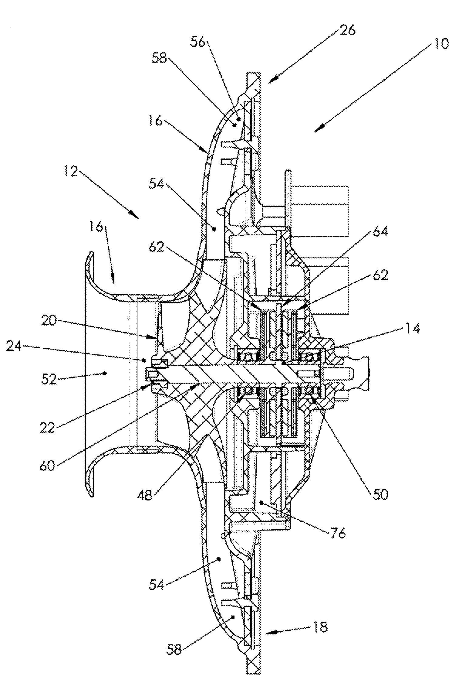
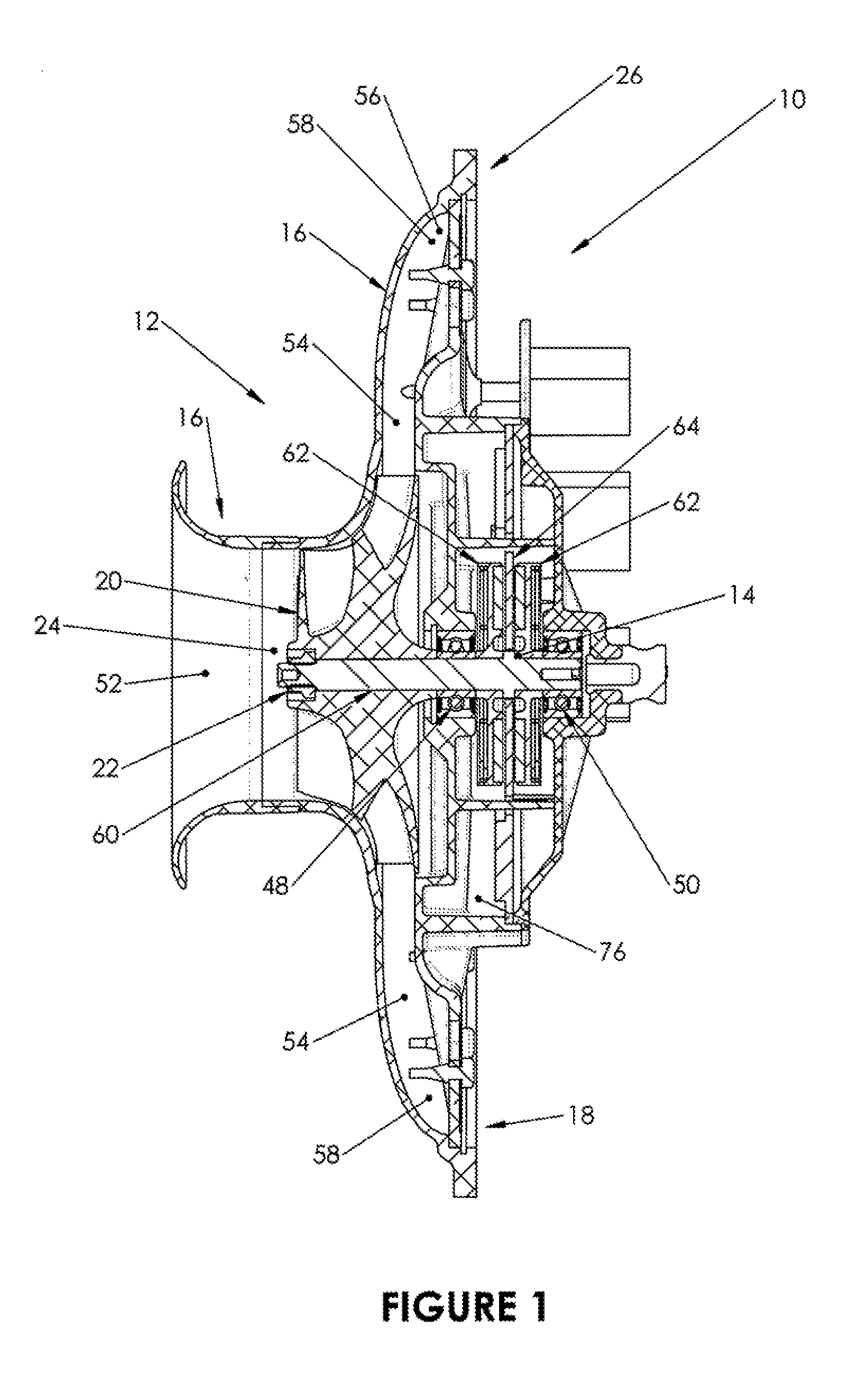
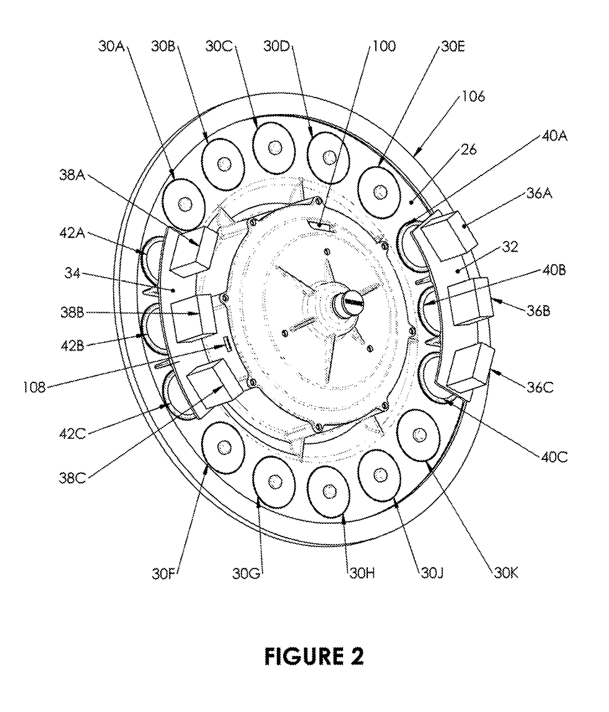
[0030]With reference to FIGS. 1-3, a first embodiment 10 of an air pumping device suitable for the buoyancy control of lighter-than-air craft is shown. The first embodiment 10 of the air pumping device features a centrifugal compressor assembly 12 and an axial gap motor 14 of axial gap, DC design, wherein both the centrifugal compressor assembly 12 and the axial gap motor 14 utilize a common shaft 60. The first embodiment 10 of the air pumping devi...


PUM


Abstract

An air pumping device for the buoyancy control of a lighter than air craft is presented. The pumping device integrates within a single housing a centrifugal compressor and an axial gap, ironless core, electric motor. All of the rotating components of the compressor and motor are mounted on a single common shaft. The air pumping device includes a valve arrangement which allows for both forward and reverse airflow though the compressor portion of the device. The motor portion of the device features a stator coil and power, communications and sensor electronics, all integrated on a single common printed circuit board. The air pumping device exhibits exceptionally high operating efficiency and power density, which are highly desirable for lighter than air craft applications.

Description

CROSS REFERENCE TO RELATED APPLICATION[0001]This application claims the benefit of U.S. provisional patent application No. 62 / 002,856 filed on May 25, 2014, the entirety of which is hereby incorporated by reference.FIELD OF THE INVENTION[0002]The present invention relates generally to devices for providing active control of the aerostatic lift of an aerostat or balloon and, more particularly, to a device for actively controlling the static lift of an aerostat or balloon by altering the ratio of air to lifting gas contained within the aerostat or balloon via pneumatic means. The present invention relates generally as well to forced air devices such as heating and cooling systems that require forced air.BACKGROUND OF THE INVENTION[0003]Balloons and aerostats employ a lifting gas, such as helium, to fill an envelope and create static lift. Early balloons and aerostats were single envelope designs, i.e. designs which featured a single envelope for the lifting gas. These craft had no abi...

Claims


Application Information

Patent Timeline
Patent Type & Authority Applications(United States)
IPC IPC(8): B64B1/62F04D29/053F04D29/32F04D19/00F04D25/06
CPCB64B1/62F04D19/002F04D29/053F04D29/32F04D25/06F04D29/325F05D2300/43
Inventor ANDERSON, ROBERT B.GRAHAM, GREGORY S.
Owner ANDERSON ROBERT B
Why Eureka
Try Eureka