Plunger pump power control device and control method thereof

a power control device and power control technology, applied in the direction of pump control, pump control, positive displacement liquid engine, etc., can solve the problems of high mass production cost, large manufacturing difficulty, sticking, etc., and achieve the effect of simple structure, less errors, and easy manufacturing

Inactive Publication Date: 2015-12-03
JIANGSU HENGLI HYDRAULIC
View PDF7 Cites 3 Cited by
  • Summary
  • Abstract
  • Description
  • Claims
  • Application Information

AI Technical Summary

Benefits of technology

[0019]By adopting the aforesaid technical solution, the present disclosure has the following benefits:
[0020](1) the power control method and device of the present disclosure allow the hydraulic plunger pump to control the output power, the pump power output is simulated by two broken lines, and the error is less. The device has a simple structure, parts that are easy to be manufactured and a low mass production cost. It is flexible to change the variables of the valve, and a high control stability on the variable is achieved.
[0021](2) the perpendicularity between the plane of the stop screwed plug that is near the valve core and the axis of the slide valve is controlled in the present disclosure so as to prevent the slide valve from being affected by a radial force.

Problems solved by technology

Because the 3-position two-way valve formed of the valve sleeve and the valve core of the aforesaid structures has two different diameters, higher requirements are imposed on the cylindricity of the valve sleeve and the valve core and the coaxiality of the two step diameters, which represents great difficulty in manufacturing and results in higher mass production cost.
Moreover, because of the objective existence of coaxiality errors between the two step diameters of each of the valve sleeve and the valve core, sticking may be caused.

Method used


Image

  • Plunger pump power control device and control method thereof
  • Plunger pump power control device and control method thereof
  • Plunger pump power control device and control method thereof

Examples


embodiment 1

A Plunger Pump Power Control Device

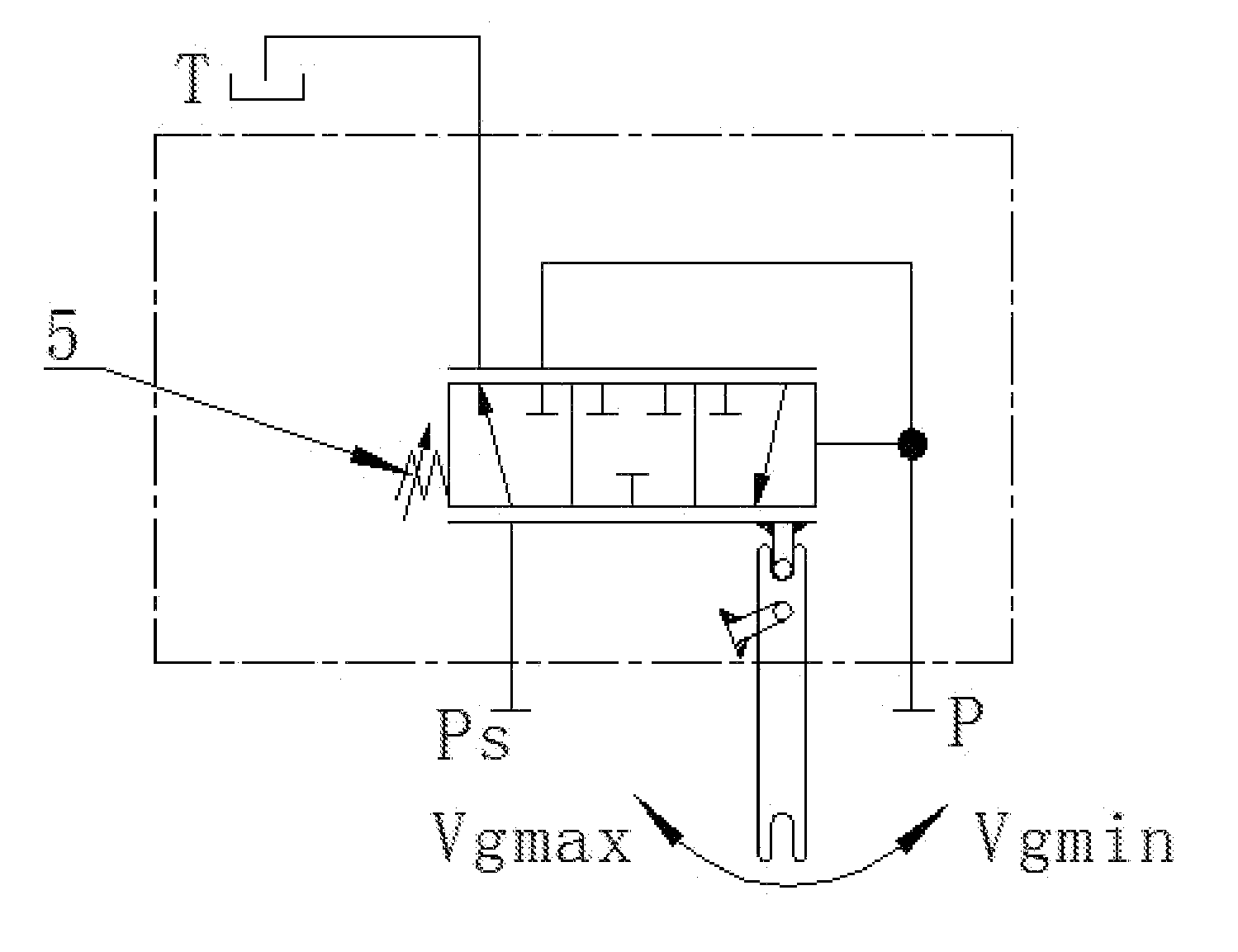
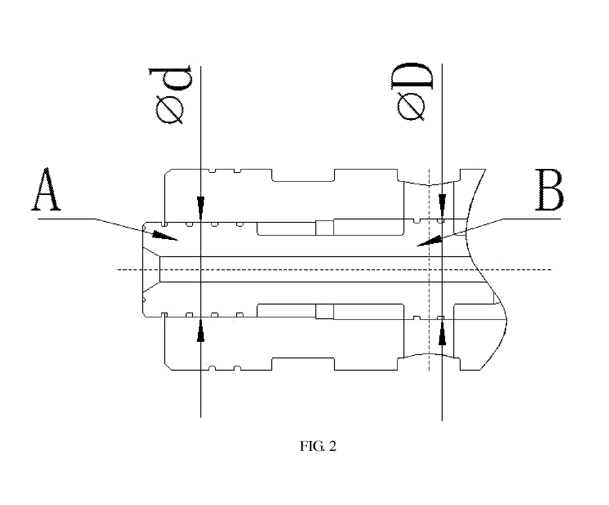
[0030]Referring to FIG. 2 to FIG. 5, a plunger pump power control device comprises a control valve body 1, a valve core 2, a valve sleeve 3, a stop screwed plug 4, a spring pre-loaded mechanism 5, a feedback mechanism 6, and a slide valve 7; an oil inlet P, an oil outlet Ps and two oil drain ports T are provided on the control valve body 1; the oil outlet Ps is externally connected to a variable piston chamber of a pump body; the valve core 2 is provided within the valve sleeve 3, the valve sleeve 3 and the valve core 2 form a 3-position two-way structure valve and an E-cavity is formed between the valve sleeve 3 and the valve core 2; the slide valve 7 is provided at the central part of one end of the valve core 2, a C-cavity is formed along a radial direction of the valve core 2 between the slide valve 7 and the valve core 2, and a ball end of the slide valve 7 contacts with the stop screwed plug 4; the stop screwed plug 4 is provided at one end o...

embodiment 2

A Control Method for a Plunger Pump Power Control Device

[0035]A control method for a plunger pump power control device specifically comprises the following steps of:

[0036](1) presetting the value of a spring pre-loaded mechanism 5;

[0037](2) introducing oil at a pump outlet pressure from an oil inlet P into a C-cavity of a valve core 2 through a valve sleeve 3, wherein the oil at the pump outlet pressure drives the slide valve 7 and the valve core 2 to move in opposite directions, the slide valve stops at a stop screwed plug, and the valve core moves towards and compresses the spring pre-loaded mechanism; or the pressure at the oil inlet P is decreased so that the spring pre-loaded mechanism drives the valve core to overcome the pressure of the C-cavity to move in a reverse direction; and

[0038](3) performing binarization processing, when the pump outlet pressure introduced into the C-cavity increases to exceed the preset value of the spring pre-loaded mechanism 5, the valve core 2 mo...


PUM


Abstract

A plunger pump power control device and a control method thereof. The device comprises a valve body, a valve core, a valve sleeve, a stop plug, a spring pre-loaded mechanism, a feedback mechanism and a slide valve. The slide valve is provided within one end of the valve core. The stop plug is provided at one end of the valve body, and the spring pre-loaded mechanism is provided at the other end of. The valve sleeve, the valve core, and the slide valve are provided between the stop plug and the spring pre-loaded mechanism, and the feedback mechanism is hinged on the valve body. The device enables the hydraulic plunger pump to control the output power, the pump power output is simulated by two broken lines, and the error is less. It is flexible to load variable by the valve core through the pressure of the C-cavity.

Description

CROSS REFERENCE TO RELATED APPLICATIONS[0001]The present application is a Continuation application of PCT application No. PCT / CN2013 / 001488 filed on Dec. 2, 2013, which claims the benefits of Chinese Patent Application No. 201310590024.2 filed on Nov. 20, 2013 and Chinese Utility Model Application No. 201320740091.3 filed on Nov. 20, 2013. All the above are hereby incorporated by reference.FIELD OF THE INVENTION[0002]The present disclosure generally relates to the technical field of machine manufacturing, and more particularly, to a plunger pump power control device and a control method thereof.BACKGROUND OF THE INVENTION[0003]Power control is a common control mode for hydraulic pumps, through which the output power of the pump can remain constant (i.e., W=PQ) within a certain working pressure range. The power control is to adjust and input oil at a pump outlet pressure into a variable piston by means of a power control device or to drain the pressure oil from the variable piston by...

Claims


Application Information

Patent Timeline
Patent Type & Authority Applications(United States)
IPC IPC(8): F04B49/22
CPCF04B49/22F04B49/08F04B2205/04
Inventor WANG, LIPINGLI, TONGHUA, HAIMINGLIN, DACHAOWEI, LEI
Owner JIANGSU HENGLI HYDRAULIC
Why Eureka
Try Eureka