
Vitrified chemically bonded phosphate ceramics for immobilization of radioisotopes

a chemical bonding and phosphate ceramic technology, applied in nuclear engineering, radioactive decontamination, etc., can solve the problems of limiting the acceptance of alternative technologies by stakeholders and other interested parties, and affecting the practical utilization of glass vitrification

Active Publication Date: 2015-12-03
UCHICAGO ARGONNE LLC
View PDF0 Cites 16 Cited by
  • Summary
  • Abstract
  • Description
  • Claims
  • Application Information

AI Technical Summary

Benefits of technology

The patent describes a way to safely handle waste materials that normally have a high volatility when heated to traditional glass vitrification temperatures. The method produces vitrified CBPC articles that have the volatile materials immobilized, minimizing the amount of material that evaporates during the process. Additionally, the toxic and radioactive components are resistant to leaching from the vitrified CBPC articles.

Problems solved by technology

The glass vitrification method has drawbacks, however.
However, several issues have hindered practical utilization this process.
Acceptance of alternative technologies by the stakeholders and other interested parties has been limited, in spite of benefits from such alternatives.
Currently, there are no official waste acceptance criteria and accepted testing procedures for alternative waste-forms, such as CBPCs, that are produced at room temperature.
Storage of high volume waste-forms is expensive, and over a period of many years the cost of vitrification and storage may turn out to be cheaper than room temperature stabilization despite initial high cost of vitrification.
Nuclear power plants generate spent nuclear fuel, which also faces the same problem during vitrification.
The burn-up level results in reduction of actinide energy in the spent fuel, but because of more fission reactions, the fission product concentration increases and hence the problem of immobilization of Cs-137 in the waste stream gets worse.
It is expected that future plants will have even higher burnup levels.
There is also another safety and security issue with Cs-137.
Even a small amount can contaminate a large body of water.

Method used


Image

  • Vitrified chemically bonded phosphate ceramics for immobilization of radioisotopes
  • Vitrified chemically bonded phosphate ceramics for immobilization of radioisotopes

Examples


example 1

Vitrified CBPC Immobilized Waste Form

[0036]Simulated Hanford tank sludge (KE basin sludge) was incorporated in CBPC and vitrified. This sludge contains trace levels of hazardous metals such as Cr, Cd, Pb, traces of actinide simulants, and non-radioactive Cs and Sr in place of the fission products Cs-137 and Sr-90, as well as oxides of major elements such as Al, Ca, Mg. Ba and the like. This simulated waste was crushed to a fine powder and was incorporated in a CBPC matrix by mixing with MgO, KH2PO4 and water in the proportions of Eq. 1, described herein. Additional samples were prepared in which the powdered simulated waste was mixed with granulated bottle glass frits in a weight ratio of about 1:9. The glass had the composition: SiO2=65-73 wt %, Al2O3=0.5-10.0 wt %, Fe2O3=0.2-3.0 wt %, CaO=5-12 wt %, MgO=0-3 wt %, P2O5=0-2 wt %, and Na2O=10-17 wt %. The resulting mixtures (with and without glass) were vitrified by heating at about 1200° C. for about one hour. The samples with and w...

example 2

Production of a Vitrified CBPC Radioactive Source with CsCl

[0037]Nonradioactive CsCl was utilized to safely simulate a radioactive CsCl source. Vitrified CBPC-Cs articles were produced with volumes of a few cubic centimeters by the methods described herein. CsCl loadings were about 10 and 15 wt % respectively. Powders of CsCl, MgO, and KH2PO4 were mixed together, and water was added to the mixture with agitation according to the stoichiometric proportion given in Eq. 1. The time interval between the beginning of agitation and solidification was about 5 to 6 minutes. The temperature rose up to 48° C. during this period. Several samples were made this way.

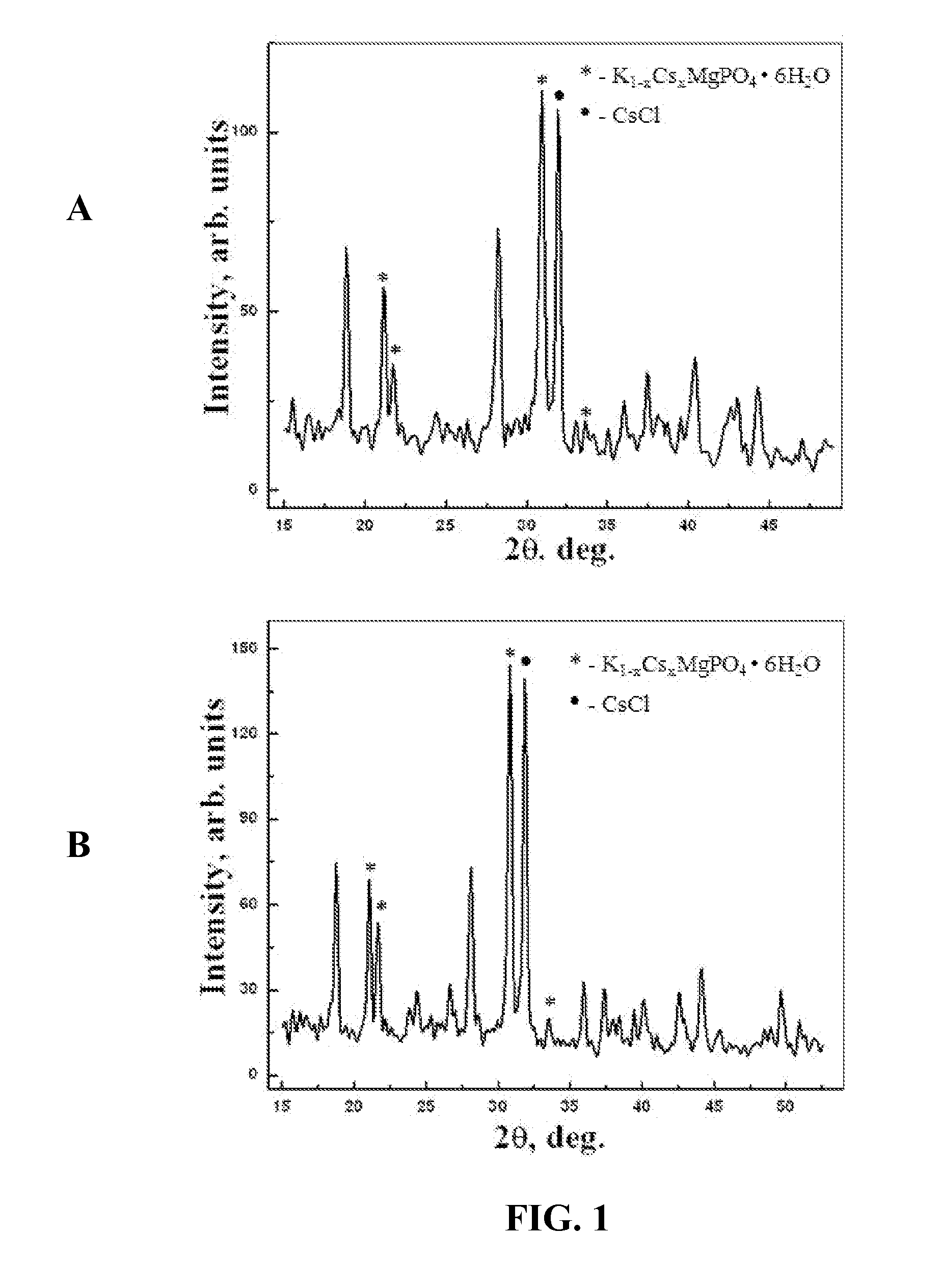
[0038]After the samples had set for about one week, small pieces of the vitrified CBPC were crushed into fine powders and subjected to X-ray diffraction. The diffraction patterns of the two samples are presented in FIG. 1. Panel A of FIG. 1 provides the results for a sample comprising 10 wt % CsCl loading, while Panel B provides the ...

example 3

Effect of High Temperature on Stability of CsCl-Containing CBPC

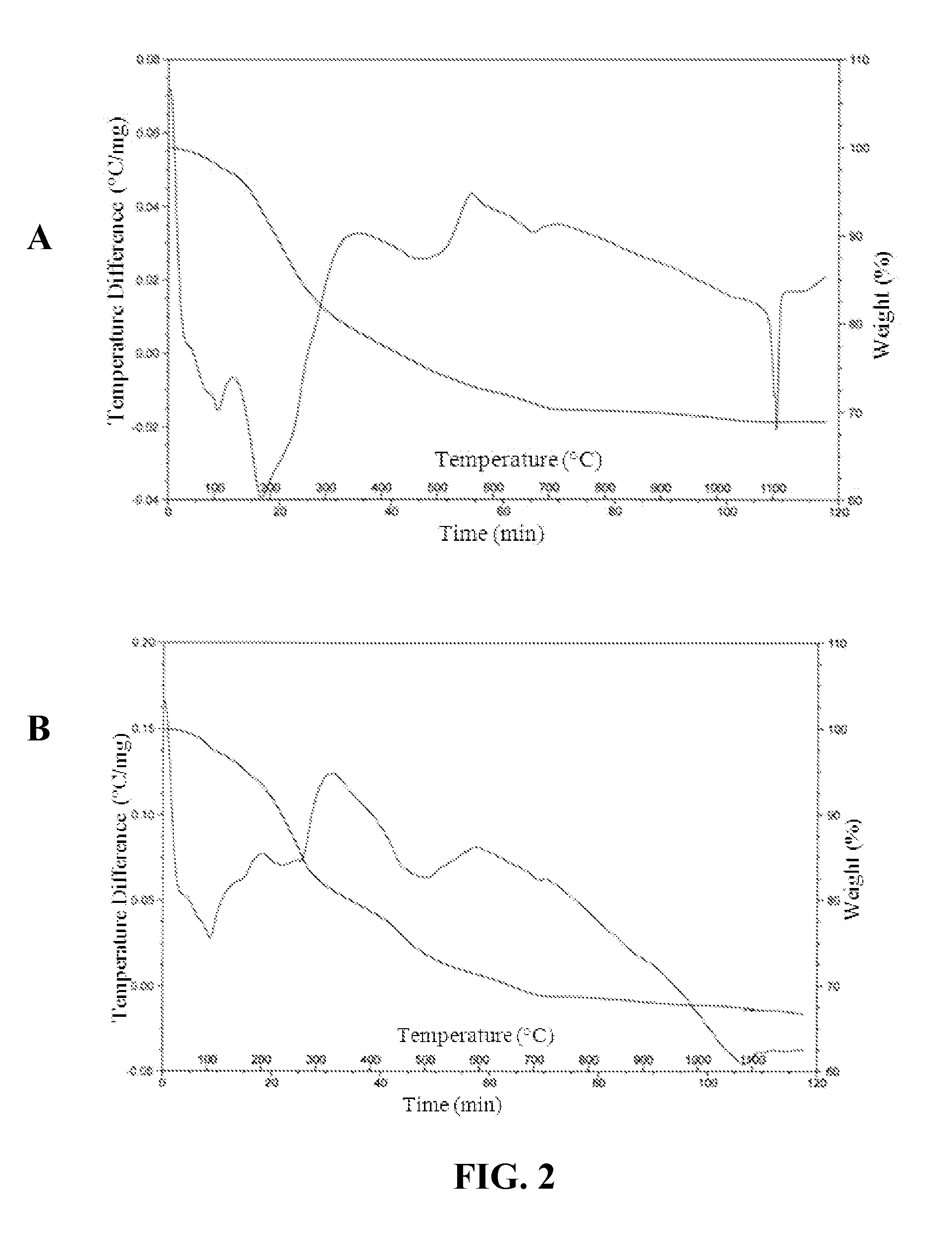
[0039]The volatility of Cs during vitrification of a CBPC matrix was evaluated using thermogravimetry. DTA / TGA data samples containing 10 wt % and 15 wt % CsCl (FIG. 2, Panels A and B, respectively) indicated that there was no weight loss by the CsCl-containing CBPC samples after heating to 1200° C. other than loss of water of crystallization in the temperature range between 0 and 700° C. Above 700° C., the sample weight remained substantially the same. Endothermic peaks were observed at temperatures of 1106° C. (FIG. 2, Panel A) and 1080° C. (FIG. 2, Panel B), which were due to the sample material melting without any mass loss.

[0040]The structure of the CsCl-containing CBPC materials were investigated using a high resolution microscope after vitrification. The CBPC samples with added cesium were subjected to heat treatment in air at about 1150° C., with a hold time of about 1 hour. The samples (about 2 to 3 grams each) ...


PUM

PropertyMeasurementUnit
temperatureaaaaaaaaaa

Abstract

A method of immobilizing a radioisotope and vitrified chemically bonded phosphate ceramic (CBPC) articles formed by the method are described. The method comprises combining a radioisotope-containing material, MgO, a source of phosphate, and optionally, a reducing agent, in water at a temperature of less than 100° C. to form a slurry; curing the slurry to form a solid intermediate CBPC article comprising the radioisotope therefrom; comminuting the intermediate CBPC article, mixing the comminuted material with glass frits, and heating the mixture at a temperature in the range of about 900 to about 1500° C. to form a vitrified CBPC article comprising the radioisotope immobilized therein.

Description

CONTRACTUAL ORIGIN OF THE INVENTION[0001]The United States Government has rights in this invention pursuant to Contract No. DE-ACO2-06CH11357 between the United States Government and UChicago Argonne, LLC representing Argonne National Laboratory.FIELD OF THE INVENTION[0002]This invention relates to vitrified chemically bonded phosphate ceramics comprising immobilized radioisotopes (e.g., fission products) and methods of immobilizing the radioisotopes therein.BACKGROUND[0003]Glass vitrification is a preferred method of immobilizing nuclear waste produced by nuclear power plants (spent nuclear fuel), and also legacy defense waste in nuclear countries such as the United States, former Soviet Union countries, France, and United Kingdom. In this vitrification method, the nuclear waste such as spent nuclear fuel and high to low level waste streams, are mixed with borosilicate, aluminum phosphate, or iron phosphate glass fits, and heated to a vitrification temperature that ranges from abou...

Claims


Application Information

Patent Timeline
Patent Type & Authority Applications(United States)
IPC IPC(8): G21F9/30C03C4/00C03C14/00G21F9/16C04B35/447
CPCG21F9/305G21F9/162C04B35/447C03C2214/20C03C4/0042C03C2214/14C03C14/008C03C14/006C04B35/62625C04B35/62685C04B2235/3201C04B2235/3206C04B2235/3418C04B2235/3454C04B2235/365C04B2235/447
Inventor WAGH, ARUN S.
Owner UCHICAGO ARGONNE LLC
Learn More