Fuel cell system and control method therefor

a fuel cell and system technology, applied in the field of fuel cell systems, can solve the problems of unable to generate power, deterioration of the diffusivity of gas passing through the electrolyte membrane, etc., and achieve the effect of suppressing the freezing of produced water

Active Publication Date: 2015-12-03
NISSAN MOTOR CO LTD
View PDF5 Cites 8 Cited by
  • Summary
  • Abstract
  • Description
  • Claims
  • Application Information

AI Technical Summary

Benefits of technology

[0004]The present invention was developed in view of such a problem. The present invention aims

Problems solved by technology

Thus, when the fuel cell system is started below freezing point, the diffusivity of gas passing through the electroly

Method used


Image

  • Fuel cell system and control method therefor
  • Fuel cell system and control method therefor
  • Fuel cell system and control method therefor

Examples


Embodiment Construction

[0012]Hereinafter, an embodiment of the present invention will be described with reference to the accompanying drawings.

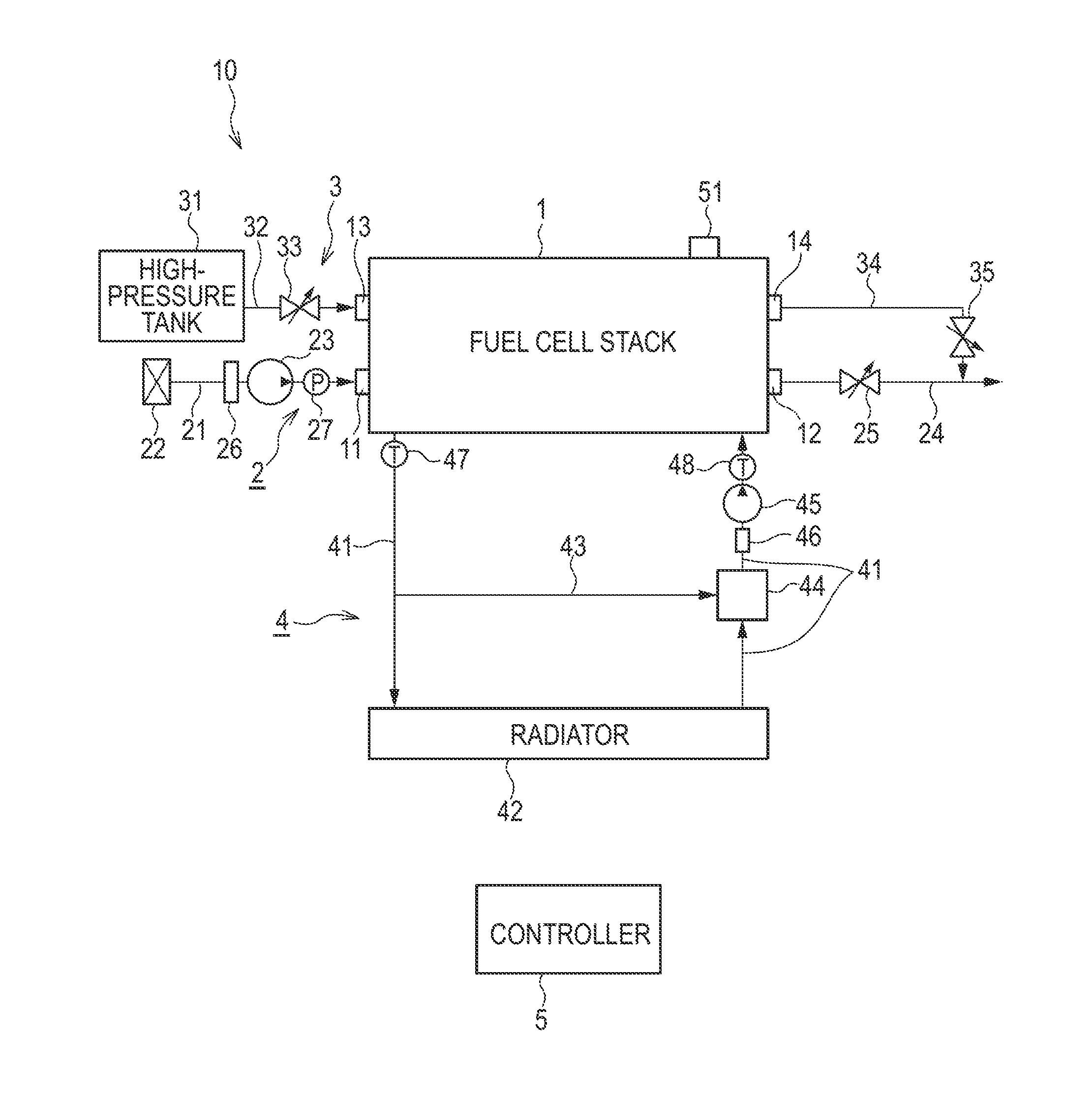
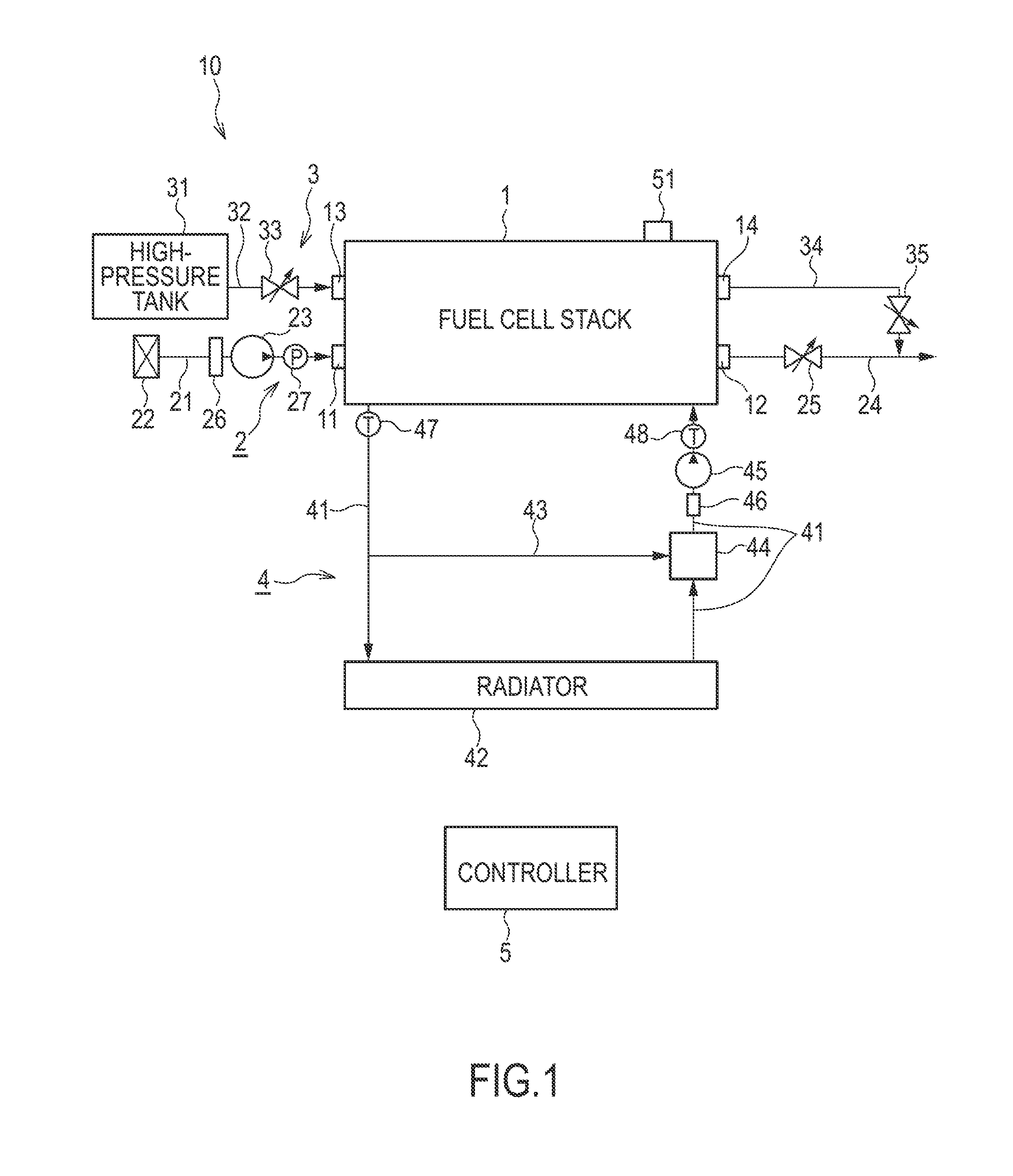
[0013]FIG. 1 is a schematic diagram showing a fuel cell system according to a first embodiment of the present invention.

[0014]A fuel cell system 10 is a system for warming up a fuel cell stack 1 utilizing self-heat generated by power generation of the fuel cell stack itself when the fuel cell stack 1 is started. The fuel cell system 10 includes the fuel cell stack 1, a cathode gas supplying / discharging device 2, an anode gas supplying / discharging device 3, a stack cooling device 4 and a controller 5. The cathode gas supplying / discharging device 2, the anode gas supplying / discharging device 3 and the stack cooling device 4 are used as auxiliary machines of the fuel cell stack 1.

[0015]The fuel cell stack 1 is formed by laminating several hundreds of fuel cells. The fuel cell stack 1 is used as a drive source for an automotive vehicle in the present embodiment.

[0016]I...


PUM


Abstract

A fuel cell system includes an auxiliary machine electrically connected to a fuel cell, the auxiliary machine being driven by power of the fuel cell, a heater electrically connected to the fuel cell, the heater being configured to heat cooling water supplied to the fuel cell, and a warm-up control unit configured to warm up the fuel cell itself by the supply of power to the auxiliary machine and the heater during start-up of the fuel cell below freezing point. The warm-up control unit includes a water amount computation unit configured to compute a produced water amount on the basis of a degree of wetness and a temperature of the fuel cell and a generated power of the fuel cell during warm-up, the produced water amount being a water amount produced in an electrolyte membrane until the temperature of the fuel cell increases to a freezing point temperature, and an anti-freezing control unit configured to increase a power ratio of power to the heater in regards to the auxiliary machine during the warm-up when the computed produced water amount is determined to be larger than a threshold value.

Description

TECHNICAL FIELD[0001]This invention relates to a fuel cell system and a control method therefor during low temperature start-up.BACKGROUND ART[0002]A temperature range suitable for power generation of a fuel cell to be mounted in a vehicle is generally about 70° C. Thus, the temperature of the fuel cell needs to be quickly increased to the temperature range suitable for power generation when starting the vehicle. JP2009-4243A discloses a fuel cell system for shortening a warm-up time of fuel cells utilizing self-heat generation that is generated by driving the fuel cells themselves to generate power.SUMMARY OF INVENTION[0003]The above fuel cell system may be started at a low temperature of −30° C., for example, depending on a vehicle's usage environment. In such a case, water produced in electrolyte membranes may exceed a water retaining amount of the electrolyte membranes and overflow in association with the self-heat generation of the fuel cells and the overflowed water is frozen ...

Claims


Application Information

Patent Timeline
IPC IPC(8): H01M8/04
CPCH01M8/04268H01M8/04253H01M8/0432H01M2250/20H01M8/04701H01M8/04955H01M8/04037H01M8/04529H01M8/04619H01M8/04947Y02E60/50Y02T90/40
Inventor HOSHI, KIYOSHI
Owner NISSAN MOTOR CO LTD
Why Eureka
Try Eureka