Ear inspection device and method of determining a condition of a subject's ear

a technology of ear inspection and eardrum, which is applied in the field of ear inspection devices and methods of determining the condition of a subject's ear, can solve the problems of radial offset of optical axis or visual axis, he or she may be informed, and the eardrum of the ear may be inflamed

Active Publication Date: 2015-12-10
HELEN OF TROY LIMITED
View PDF12 Cites 23 Cited by
  • Summary
  • Abstract
  • Description
  • Claims
  • Application Information

AI Technical Summary

Problems solved by technology

In contrast, a radial offset of the optical axis or visual axis would not be effective in case the electronic imaging unit or the infrared sensor unit is not arranged most distal.
Instead, the measured elevated temperature may result from a local inflammation of the eardrum of the ear into which the device has been introduced.
In particular, he or she may be informed that a reliable temperature measurement is not possible (since there is no free line of sight between the infrared sensor unit and the eardrum).
Immobilization of the eardrum can result either from fluid or from abnormal, especially low air pressure behind the eardrum.
Another problem with otoscopes known in the art is that the ear has to be significantly deformed—which is uncomfortable or even causes pain to the subject—in order to have a direct view onto the eardrum.
Furthermore, there is a risk of introducing the otoscope too far into the subject's interior ear canal thereby causing pain and injuries to the ear canal, and in particular to the eardrum.
In particular in the case of young children—where the inner part of the ear canal is relatively short and sudden head movement during the examination may occur—there is a risk of penetration of the very sensitive ear canal skin or even of the eardrum ED.
Moreover, especially in an inflamed ear, the mechanical manipulation of “straightening” the ear canal C, especially by introducing the distal end far into the bony part of the ear canal, typically causes considerable discomfort or even pain, rendering the examination of an infant even more difficult.
For the above reasons, reliable and secure handling of an otoscope of the art is currently subject to only well trained physicians and not amenable to the larger community of practitioners.
A study recently published in the US as a result of a survey has shown that even physicians often fail to (correctly) determine the status of e.g. the subject's eardrum or fail to correctly interpret the image provided by the otoscope (i.e. correct and meaningful object recognition).
Such failures result in misinterpretation of the status of the inner ear canal or the eardrum.
As a consequence, e.g. over-medication with antibiotics for treating supposed inflammations of the eardrum occurs, because physicians tend to err on the side of caution, or meaningless image interpretation occurs.
Injuring the inner part of the ear canal even bears the risk of cardiovascular complications through vagal overstimulation.
Furthermore, the longitudinal force upon introduction into the ear canal can be limited by a telescoping mechanism or the use of an elastic element.
When introducing the tip end of the head portion no deeper into the ear canal than to the border between the outer part and the inner part of the outer ear canal of the subject's outer ear, there is the risk that artifacts, such as earwax, hair and other kind of dirt from the outer part of the outer ear canal, obstruct the view of the small electronic imaging unit onto the eardrum.
Otherwise, artifacts, such as earwax particles, adhering to the probe cover will obstruct a free view onto the eardrum, even if the electronic imaging unit and / or the infrared sensor unit is / are displaced by the motion mechanism.

Method used


Image

  • Ear inspection device and method of determining a condition of a subject's ear
  • Ear inspection device and method of determining a condition of a subject's ear
  • Ear inspection device and method of determining a condition of a subject's ear

Examples


Embodiment Construction

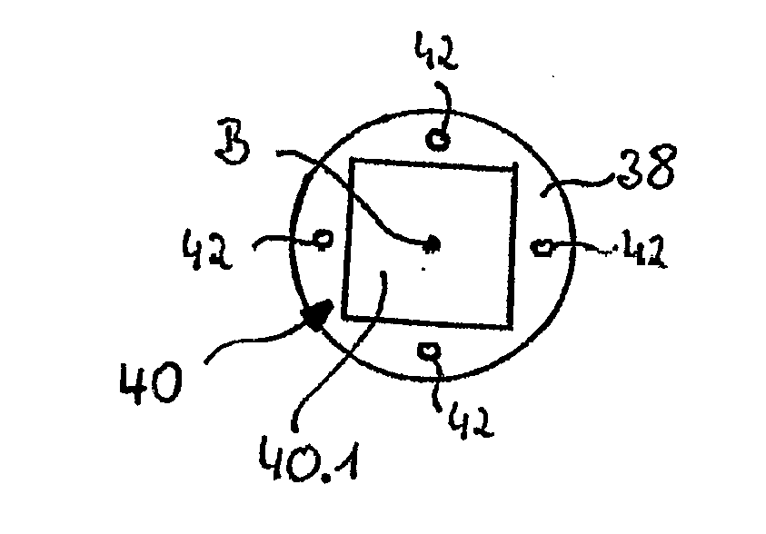
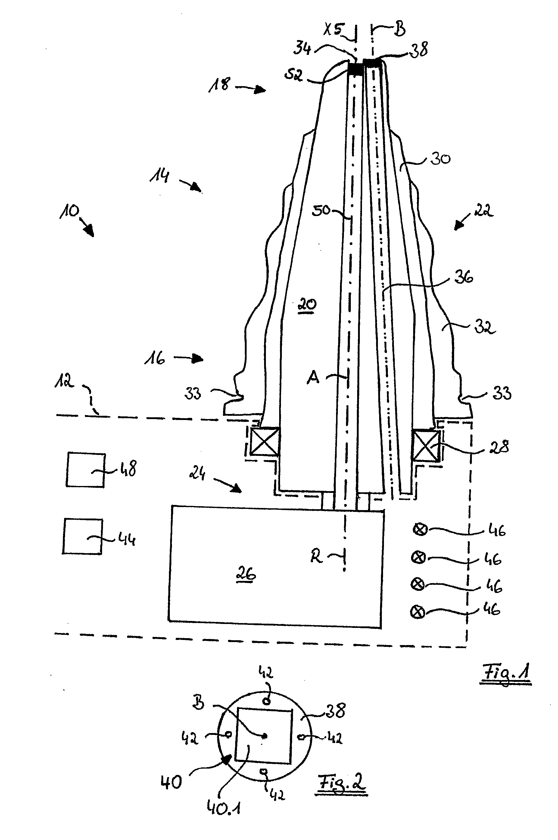
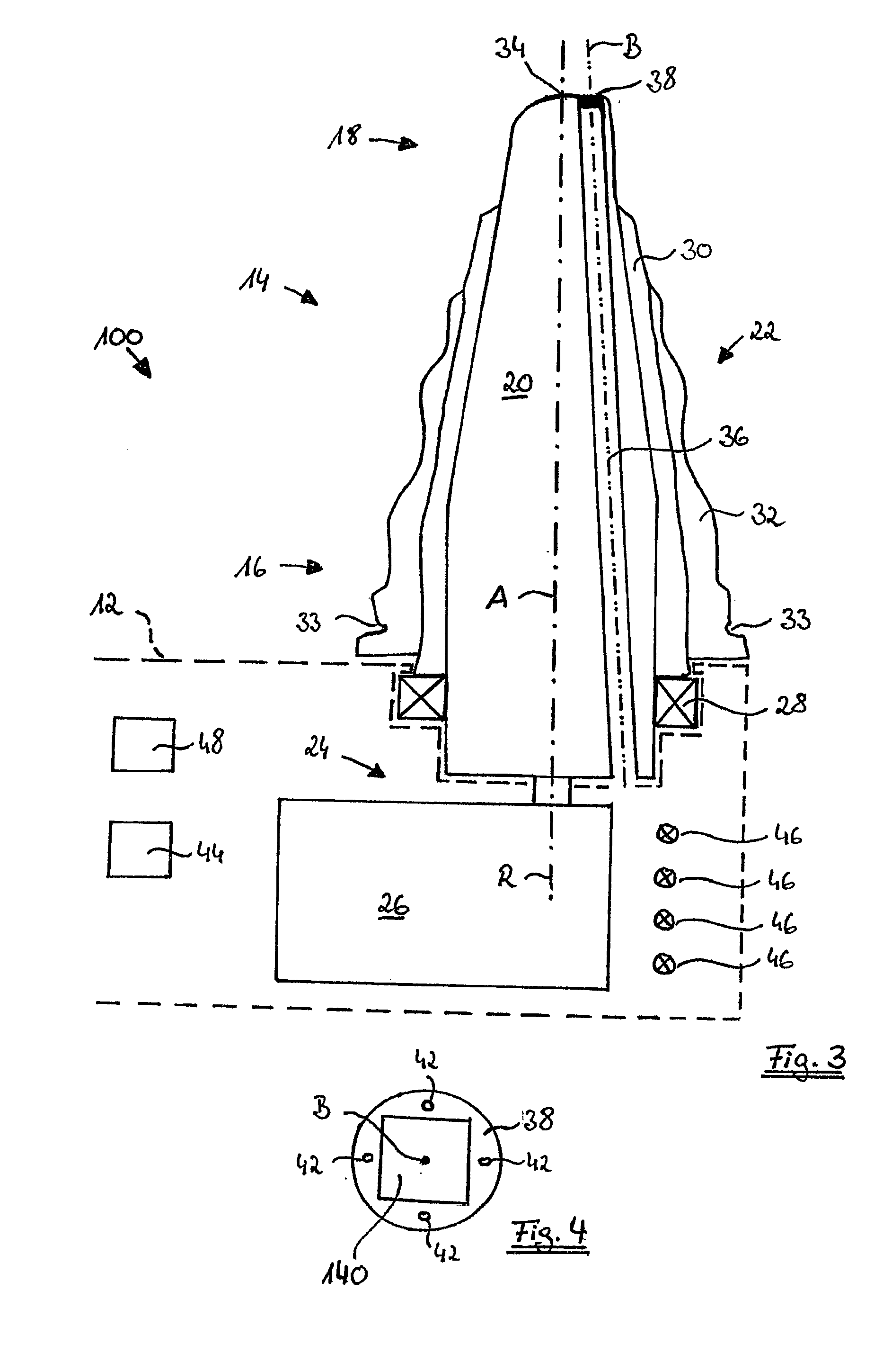
[0155]FIG. 1 schematically shows a cross-sectional view of a head portion 14 and a part of a handle portion 12 (only shown in phantom lines) of a first embodiment of an ear inspection device 10 according to the present invention. As can be seen from FIG. 1, the head portion 14 has a substantially tapering form extending along a longitudinal axis A of the head portion 14. The head portion 14 comprises a relatively large proximal end 16 adjacent to the handle portion 12 and a smaller distal end 18. The distal end 18 of the head portion 14 is adapted to be introduced into a subject's ear canal.

[0156]Furthermore, the head portion 14 comprises a rotatable, radial inner portion 20 and a fixed, radial exterior portion 22. The rotatable portion 20 is rotatable about an axis of rotation R which—in the shown exemplary embodiment—corresponds to the longitudinal axis A of the head portion 14. A motion mechanism 24 comprising a servo motor 26 is positioned within the handle portion 12 and is cou...


PUM


Abstract

An ear inspection device configured for being at least partially introduced into an external ear canal for determining an ear condition, such as temperature, in particular at the subject's eardrum, wherein the device comprises an infrared sensor unit configured for detecting infrared radiation from the ear, and an electronic imaging unit configured for capturing images based on radiation in the visible range from the ear, wherein the electronic imaging unit exhibits at least one optical axis arranged such that it can be radially offset within the ear canal, and wherein the infrared sensor unit exhibits a visual axis arranged such that it can be positioned centrically within the ear canal or radially offset within the same semicircle, especially the same quadrant, of the cross section of the ear canal.

Description

FIELD OF THE INVENTION[0001]According to one aspect, the invention refers to an ear inspection device configured for being at least partially introduced into a subject's external ear canal for determining a condition of the subject's ear, such as temperature, in particular at the subject's eardrum, wherein the ear inspection device comprises an infrared sensor unit configured for detecting infrared radiation from the subject's ear.[0002]Such ear inspection devices are known e.g. as radiation thermometers, infrared thermometers or ear thermometers. A corresponding thermometer is disclosed, for example in the US patent document U.S. Pat. No. 6,898,457 B1 assigned to Braun GmbH. Such thermometers—not only used by physicians or other health care professionals but also by lay persons in the domestic field—have become more and more popular in recent years because the body core temperature can be determined very fast within only a few seconds with such a thermometer, and because measuring ...

Claims


Application Information

Patent Timeline
Patent Type & Authority Applications(United States)
IPC IPC(8): A61B5/00A61B5/11A61B1/06A61B1/05A61B1/00A61B5/01A61B1/227
CPCA61B5/0086A61B5/01A61B5/6817A61B5/7264A61B5/7246A61B5/11A61B2562/0242A61B1/05A61B1/00066A61B1/0638A61B1/00009A61B5/7275A61B1/2275A61B1/00179A61B1/00193A61B1/051A61B1/227A61B5/065A61B5/6885A61B5/6886A61B1/00057A61B1/0623A61B5/0075A61B1/00101A61B1/00142A61B1/0676A61B1/0684A61B1/07A61B5/1077A61B5/7203A61B5/7221A61B5/74
Inventor RUPPERSBERG, PETERLEPPLE-WIENHUES, ALBRECHT
Owner HELEN OF TROY LIMITED
Why Eureka
Try Eureka