Oil pump
a variable capacity, oil pump technology, applied in the direction of liquid fuel engines, machines/engines, rotary/oscillating piston pump components, etc., can solve the problems of slow adjustment of the adjustment ring, reduced response of the control on the pump capacity, etc., to speed up the operation, reduce the flow resistance of the oil going back and forth between two spaces, and reduce the resistance
- Summary
- Abstract
- Description
- Claims
- Application Information
AI Technical Summary
Benefits of technology
Problems solved by technology
Method used
Image
Examples
second example
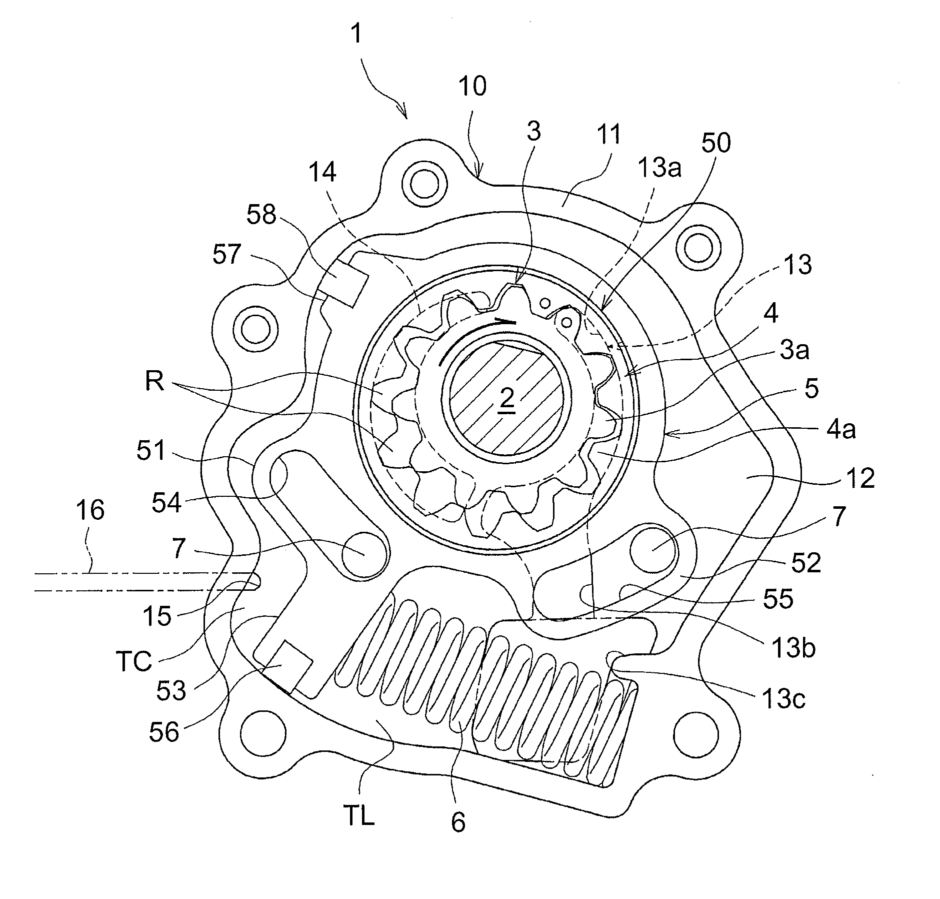
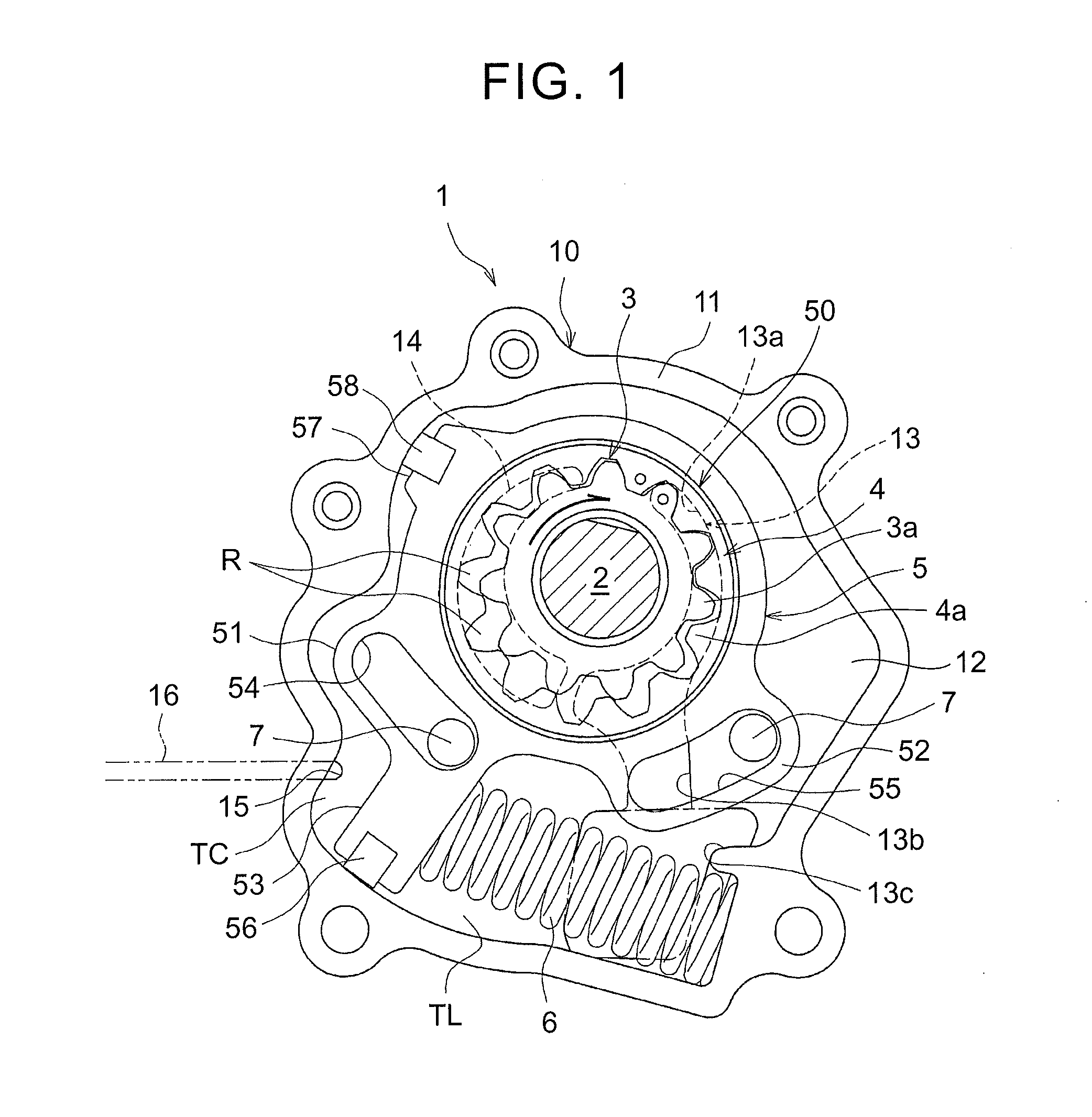
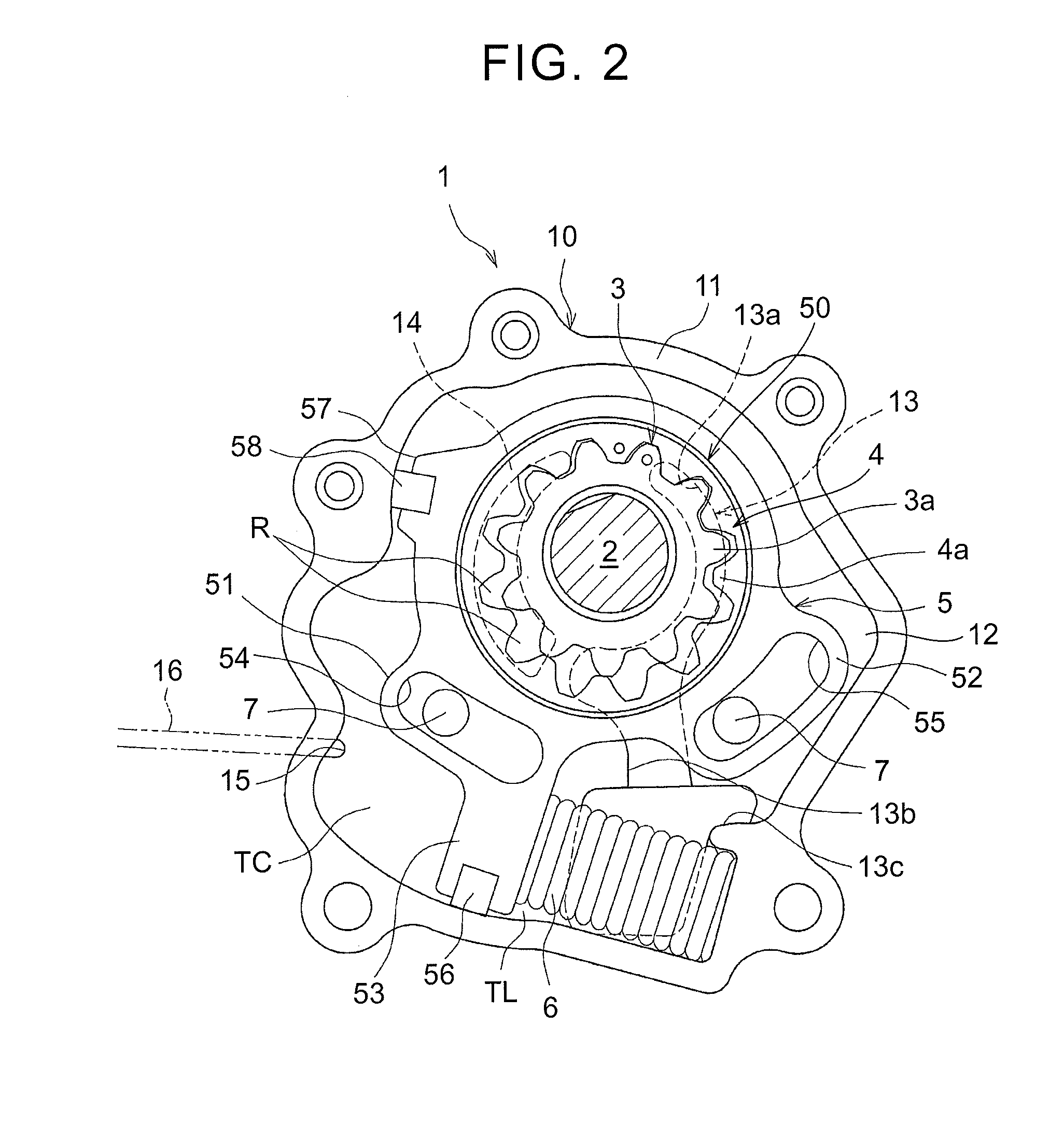
[0069]FIGS. 4A, 4B illustrate a second example in which a pair of grooves 71, 71 is formed on an outer periphery of an axially intermediate part (partially) of a guide pin 7 at a generally semicircular interval, so that the intermediate part is provided as a small sectional area part having a sectional area smaller than that of the other part. The pair of grooves 71, 71 may be also formed integrally in a manufacturing process of the guide pin 7, or may be machined. Further, it is preferable that a sectional area of each of the grooves 71 be set to be larger than a sectional area of a gap between a guide surface on an outer periphery of the guide pin 7 and a guided surface on an inner periphery of a guide slot 54.
[0070]The guide pin 7 thus provided with the grooves 71 is attached to a housing 10 so that orientations in which the grooves 71 extend are along a longitudinal direction of the guide slot 54, 55. Hereby, the grooves 71 each serve as a communicating passage that communicates...
third example
[0072]FIGS. 5A, 5B illustrate a third example in which a tip end side (an upper side in FIG. 5B) of a guide pin 7 is provided as a small sectional area part and as a tapered part 7b (a sectional-area gradually changing part), so that a space 72 around the tapered part 7b serves as a communicating passage. The tapered part 7b may be also formed integrally in a manufacturing process of the guide pin 7 or may be machined. Alternatively, the guide pin 7 itself may be formed integrally with a bottom of a receptacle recessed portion 12 of a housing 10 at the time of casting the housing 10. In this case, since the tip end side of the guide pin 7 is the tapered part 7b, demolding is performed easily.
[0073]In this example, similarly to the first example, the space 72 (a reference sign is shown only in FIG. 5B) around the tapered part 7b (the small sectional area part) of the guide pin 7 serves as the communicating passage, so that oil flows therethrough, which makes it possible to reduce a f...
fourth example
[0075]FIGS. 6A, 6B illustrate a fourth example in which a communicating passage (a through hole 73) is provided so as to penetrate through a guide pin 7. The through hole 73 may be also formed integrally in a manufacturing process of the guide pin 7 or may be machined. Even in this example, oil flows through the communicating passage (the through hole 73), so that a flow resistance thereof can be reduced.
[0076]In the fourth example, a whole outer peripheral surface of the guide pin 7 serves as a guide surface and makes sliding contact with an inner peripheral surface (a guided surface) of a guide slot 54, so that a guiding function is easy to be secured. However, similarly to the second example, it is necessary for the guide pin 7 to be attached to a housing 10 so that an orientation in which the through hole 73 extends is along a longitudinal direction of the guide slot 54, 55. Note that it is preferable that a sectional area of the through hole 73 be set to be larger than a sectio...
PUM
 Abstract
Description
Claims
Application Information
 - R&D
- Intellectual Property
- Life Sciences
- Materials
- Tech Scout
- Unparalleled Data Quality
- Higher Quality Content
- 60% Fewer Hallucinations
Browse by: Latest US Patents, China's latest patents, Technical Efficacy Thesaurus, Application Domain, Technology Topic, Popular Technical Reports.
© 2025 PatSnap. All rights reserved.Legal|Privacy policy|Modern Slavery Act Transparency Statement|Sitemap|About US| Contact US: help@patsnap.com


