[0007]The present invention was made in view of the background art described above. It is therefore an object of the present invention to provide a power transmitting system of a vehicle, which permits speedy starting of the vehicle after switching of the power transmitting system from its parking lock position to its non-parking-lock position, and which prevents a risk of deterioration of durability of a differential mechanism during
towing or traction of the vehicle.
[0009]According to the first aspect of the invention described above, the dog clutch is mechanically held in the engaged state while the power transmitting system is placed in the parking lock position, so that a synchromesh mechanism and a hub sleeve of the dog clutch remain aligned in phase with each other and are ready for the dog clutch to be placed in the engaged state (i.e., remain aligned as the dog clutch is released), even if the dog clutch is once switched to the released state when the vehicle is started after the power transmitting system is switched to the non-parking-lock position, whereby the dog clutch can be subsequently speedily brought into the engaged state, without occurrence of the so-called “up-lock”. Accordingly, the vehicle can be speedily started after the power transmitting system is switched to the non-parking-lock position. In addition, the dog clutch is not mechanically held in the engaged state while the power transmitting system is placed in the non-parking-lock position, so that it is possible to avoid a large difference among rotating speeds of the rotary elements of the differential mechanism in the released state of the dog clutch when the vehicle is towed in the non-parking-lock position (
neutral position) of the power transmitting system. It is therefore possible to prevent a risk of deterioration of durability of the differential mechanism during
towing of the vehicle.
[0011]The object indicated above is also achieved according to a third aspect of the invention, which provides a power transmitting system of a vehicle, comprising a differential mechanism, a clutch mechanism, a power transmitting mechanism, a dog clutch, a clutch switching member, and a parking lock switching member, which are disposed between an input rotary member provided to receive a drive force from a drive power source of the vehicle and an output rotary member provided to transmit the drive force to drive wheels of the vehicle, the above-described differential mechanism including an input rotary element, an output rotary element and a reaction rotary element, the above-described clutch mechanism selectively connecting two rotary elements of the above-described input, output and reaction rotary elements of the above-described differential mechanism, to each other, the above-described power transmitting mechanism having a predetermined
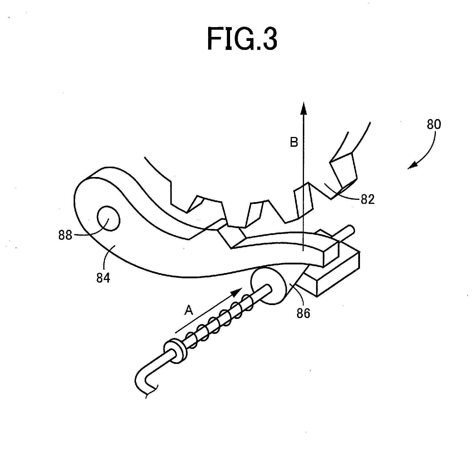
gear ratio, the above-described dog clutch being configured to selectively place a power transmitting path between the above-described output rotary element and the above-described output rotary member, in a power transmitting state and a power cutoff state, the above-described clutch switching member being configured to switch the above-described dog clutch between an engaged state and a released state, and the above-described parking lock switching member being configured to switch the power transmitting system between a parking lock position for mechanically inhibiting a rotary motion of the above-described output rotary member, and a non-parking-lock position for mechanically permitting the rotary motion of the above-described output rotary member, and wherein the above-indicated drive force is transmitted to the above-described drive wheels while the above-described clutch mechanism is placed in an engaged state and while the above-described dog clutch is placed in the engaged state, the power transmitting system being characterized in that: the above-described clutch switching member includes a protrusion; the above-described parking lock switching member includes a hook portion which is held in engagement with the above-described protrusion of the above-described clutch switching member located at a position for placing the above-described dog clutch in the engaged state when the power transmitting system is placed in the parking lock position, and is not held in engagement with the above-described protrusion when the power transmitting system is placed in the non-parking-lock position; and the above-described protrusion prevents a movement of the above-described clutch switching member toward a position for placing the above-described dog clutch in the released state, when the protrusion is held in engagement with the above-described hook portion of the above-described parking lock switching member.
[0012]According to the third aspect of the invention, the dog clutch is mechanically held in the engaged state while the power transmitting system is placed in the parking lock position, so that a synchromesh mechanism and a hub sleeve of the dog clutch remain aligned in phase with each other and are ready for the dog clutch to be placed in the engaged state (i.e., remain aligned as the dog clutch is released), even if the dog clutch is once switched to the released state when the vehicle is started after the power transmitting system is switched to the non-parking-lock position, whereby the dog clutch can be subsequently speedily brought into the engaged state, without occurrence of the so-called “up-lock”. Accordingly, the vehicle can be speedily started after the power transmitting system is switched to the non-parking-lock position. In addition, the dog clutch is not mechanically held in the engaged state while the power transmitting system is placed in the non-parking-lock position, so that it is possible to avoid a large difference among rotating speeds of the rotary elements of the differential mechanism in the released state of the dog clutch when the vehicle is towed in the non-parking-lock position (
neutral position) of the power transmitting system. It is therefore possible to prevent a risk of deterioration of durability of the differential mechanism during
towing of the vehicle.
[0013]According to a fourth aspect of the invention, the power transmitting system according to the third aspect of the invention is configured such that the above-described protrusion functions to provide a
ratchet device which permits a movement of the above-described clutch switching member relative to the above-described hook portion toward the position for placing the above-described dog clutch in the engaged state, and prevents the movement of the clutch switching member toward the position for placing the dog clutch in the released state. According to this fourth aspect of the invention, the dog clutch is mechanically held in the engaged state in an adequate manner while the power transmitting system is placed in the parking lock position, and the dog clutch is switched in an adequate manner from the engaged state to the released state when the power transmitting system is switched to the non-parking-lock position. In addition, the dog clutch can be switched from the released state to the engaged state even while the parking lock switching member is placed in the position for placing the power transmitting system in the parking lock position, so that the dog clutch can be switched from the released state to the engaged state when the power transmitting system is switched to the parking lock position after the vehicle has been towed.
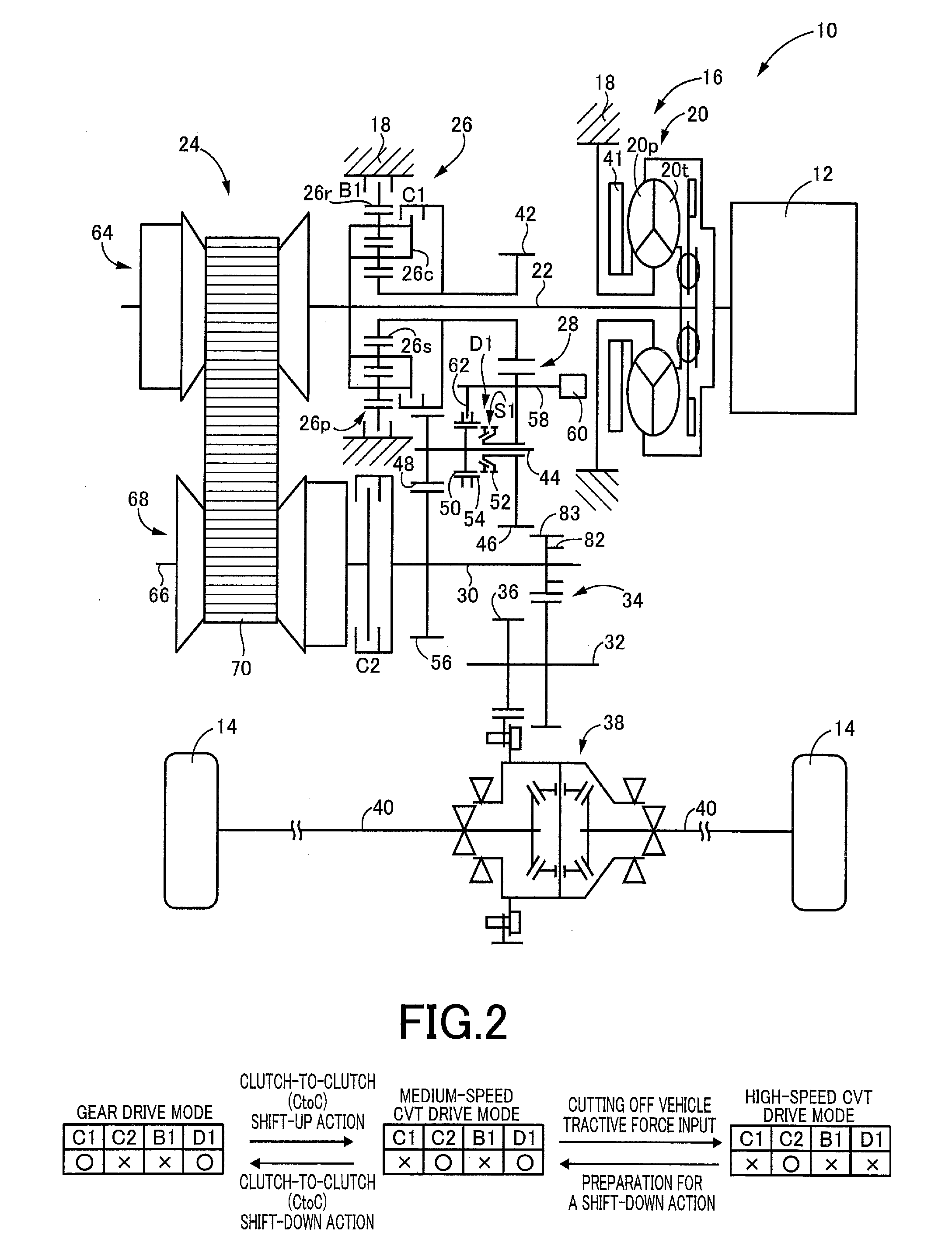
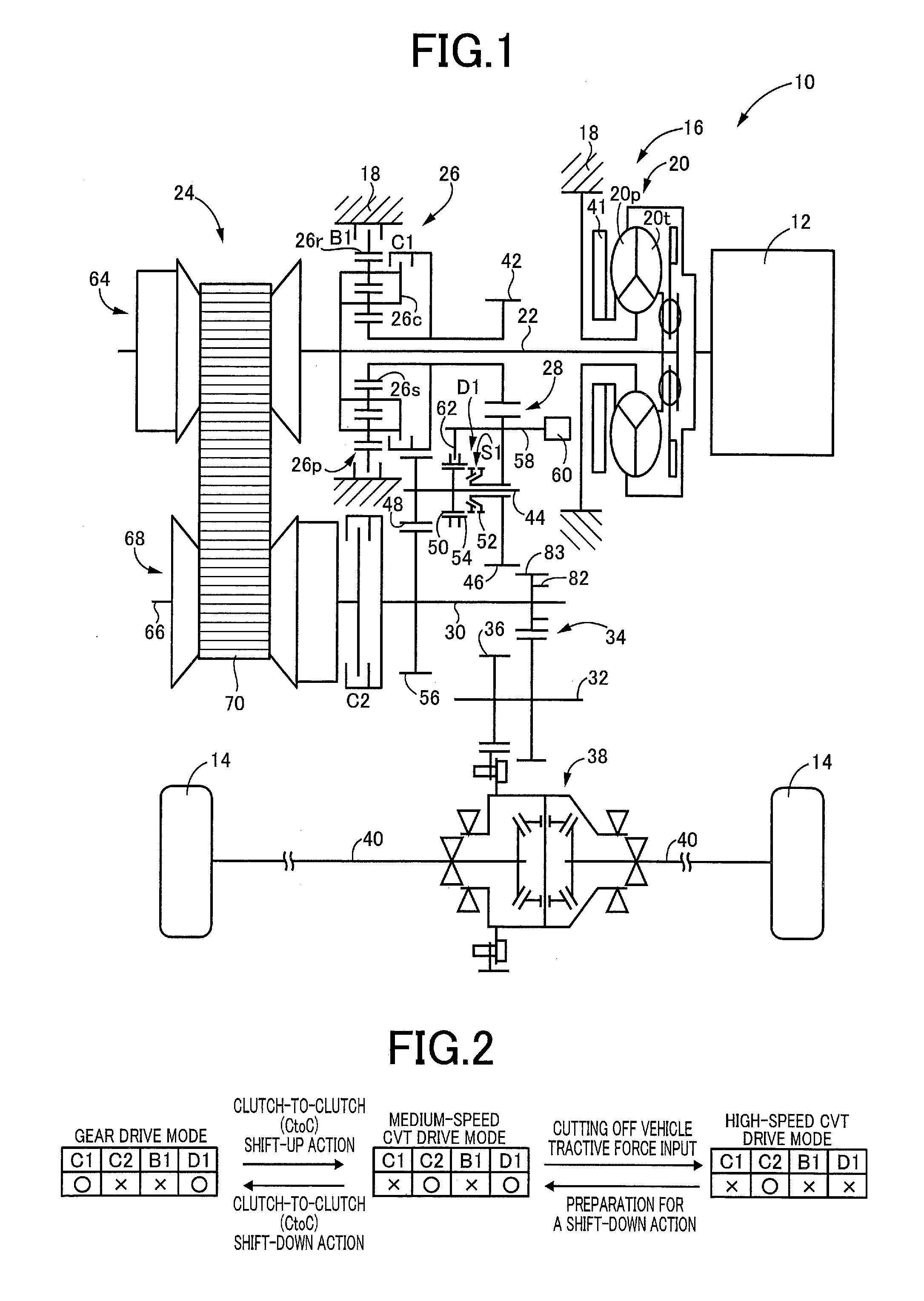
[0014]According to a fifth aspect of the invention, the power transmitting system according to any one of the first through fourth aspect of the invention further comprises a
continuously variable transmission disposed in parallel with the above-described power transmitting mechanism, between the above-described input rotary member and the above-described output rotary member, and a first clutch configured to selectively place a first power transmitting path through which the drive force is transmitted from the above-described drive power source to the above-described drive wheels through the above-described
continuously variable transmission, in a power transmitting state and in a power cutoff state. The power transmitting system is further configured such that the power transmitting mechanism has at least one gear position, and the above-described differential mechanism is disposed in a second power transmitting path through which the drive force is transmitted from the drive power source to the drive wheels through the above-described power transmitting mechanism, the above-described clutch mechanism selectively places the above-described second power transmitting path in a power transmitting state and in a power cutoff state, and the above-described dog clutch is disposed between the above-described clutch mechanism and the above-described output rotary member, to selectively place the above-described second power transmitting path in the power transmitting and power cutoff states. In the power transmitting system according to this fifth aspect of the invention wherein the
continuously variable transmission and the power transmitting mechanism are disposed in parallel with each other between the input and output rotary members, the vehicle can be speedily started after the power transmitting system is switched to the non-parking-lock position, and the deterioration of durability of the differential mechanism during towing of the vehicle can be avoided.

