Magnetic resonance imaging apparatus and method for reducing unnecessary contrast

a magnetic resonance imaging and unnecessary contrast technology, applied in the field of nuclear magnetic resonance imaging, can solve the problem of insufficient signal strength in the echo near the end, and achieve the effect of reducing unnecessary contrast and achieving intended contras

Active Publication Date: 2015-12-10
FUJIFILM HEALTHCARE CORP
View PDF4 Cites 9 Cited by
  • Summary
  • Abstract
  • Description
  • Claims
  • Application Information

AI Technical Summary

Benefits of technology

[0017]According to the present invention, it is possible to obtain a high-quality image, in which the intended contrast is e...

Problems solved by technology

Accordingly, if the echo train is too long, the sig...

Method used


Image

  • Magnetic resonance imaging apparatus and method for reducing unnecessary contrast
  • Magnetic resonance imaging apparatus and method for reducing unnecessary contrast
  • Magnetic resonance imaging apparatus and method for reducing unnecessary contrast

Examples


first embodiment

[0038]Hereinafter, a first embodiment to which the present invention is applied will be described. Hereinafter, in all diagrams for explaining the embodiments of the present invention, the same reference numerals are given to components having the same functions, and repeated explanation thereof will be omitted.

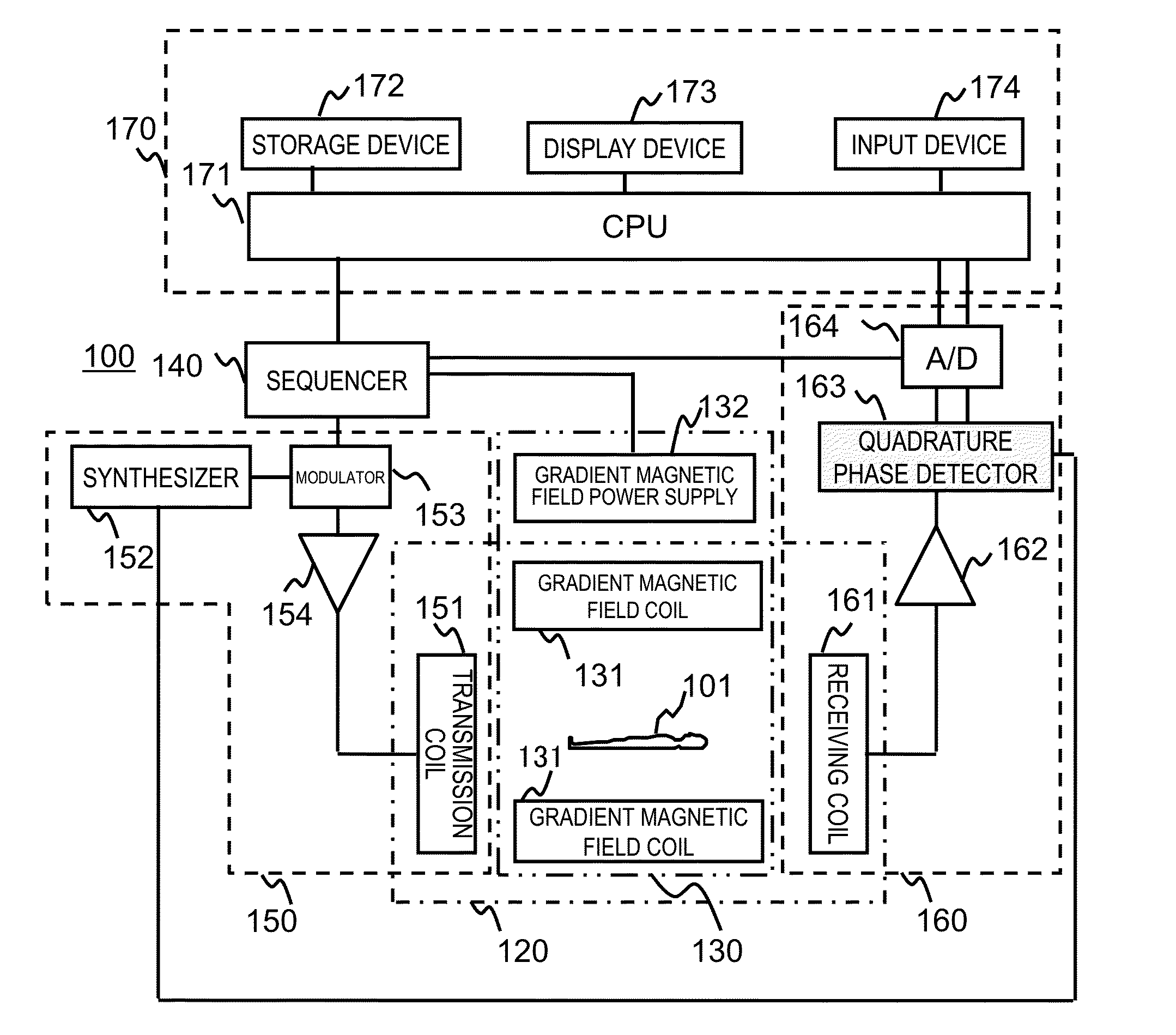
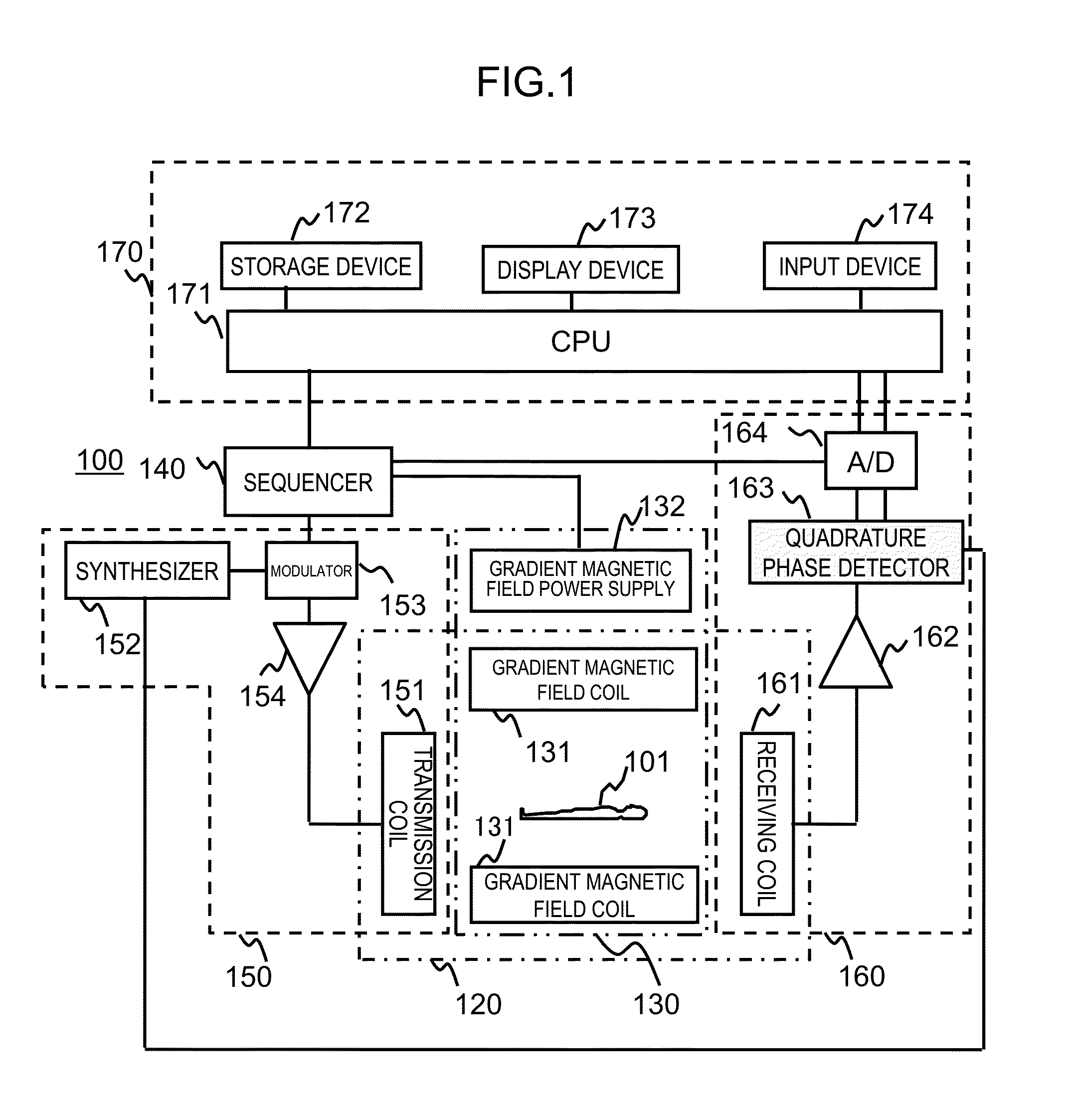
[0039]First, the overview of an example of an MRI apparatus 100 of the present embodiment will be described with reference to FIG. 1. FIG. 1 is a block diagram showing the overall configuration of the MRI apparatus 100 of the present embodiment. The MRI apparatus 100 of the present embodiment obtains a tomographic image of an object 101 using the NMR phenomenon. As shown in FIG. 1, the MRI apparatus 100 includes a static magnetic field generation unit 120 that generates a static magnetic field, a gradient magnetic field generation unit 130 that applies a gradient magnetic field to the object 101 placed in the static magnetic field, a signal transmission unit 150 that transmit...

second embodiment

[0157]Next, a second embodiment to which the present invention is applied will be described. In the first embodiment, when acquiring the T2-weighted image, adjustment parameters are adjusted so as to reduce the influence of T1. On the other hand, in the present embodiment, when acquiring the T1-weighted image, adjustment parameters are adjusted so as to reduce the influence of the T2 contrast.

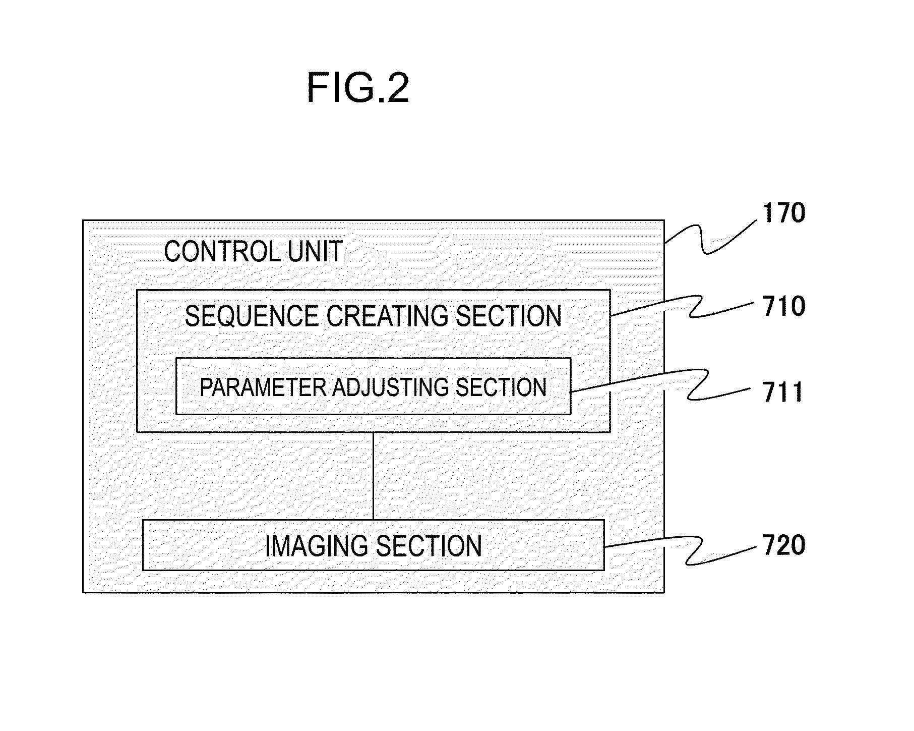
[0158]An MRI apparatus of the present embodiment has basically the same configuration as the MRI apparatus 100 of the first embodiment. The functional configuration of the control unit 170 of the present embodiment is also the same. However, since the images to be acquired are different and the contrasts to be reduced are different as mentioned above, the parameter adjustment process of the parameter adjusting section 711 is different. The pulse sequence to be used and the flow of the imaging process are the same as those in the first embodiment.

[0159]The parameter adjusting section 711 of the ...


PUM


Abstract

In multi-echo imaging, in imaging in which pulses other than a 180° pulse are included in refocus RF pulses, a high-quality image in which the intended contrast is emphasized is obtained by reducing unnecessary contrast. Therefore, imaging parameters are adjusted so as to reduce the unnecessary contrast. The adjustment is performed so that, for echo signals from tissues having the same relaxation time to cause intended contrast among echo signals from a plurality of tissues having different relaxation times, the difference between the signal strengths of echo signals to determine the contrast, such as echo signals at the k-space center, is reduced. Imaging parameters to be adjusted include a repetition time, the FA of a DE pulse, the FA of a saturation pulse, the application timing of the saturation pulse, the application strength of a gradient magnetic field in a recovery period, application timing, and the like.

Description

TECHNICAL FIELD[0001]The present invention relates to a nuclear magnetic resonance imaging (hereinafter, referred to as “MRI”) technique of measuring a nuclear magnetic resonance (hereinafter, referred to as “NMR”) signal from hydrogen, phosphor, or the like in an object and imaging nuclear density distribution, relaxation time distribution, or the like, and in particular, to a technique of adjusting the contrast of an image.BACKGROUND ART[0002]The MRI apparatus is an apparatus that measures an NMR signal generated by the object, especially, the spins of nuclei which form human tissue, and images the shapes or functions of the head, abdomen, limbs, and the like in a two-dimensional manner or in a three-dimensional manner. In the imaging, NMR signals are subjected to different phase encoding by the gradient magnetic field and subjected to frequency encoding, and are measured as time-series data. The measured NMR signals are reconstructed as an image by a two-dimensional or three-dime...

Claims


Application Information

Patent Timeline
IPC IPC(8): G01R33/561G01R33/56G01R33/36G01R33/54G01R33/48G01R33/385
CPCG01R33/5617G01R33/4818G01R33/5602G01R33/36G01R33/543G01R33/385A61B5/055G01R33/546
Inventor KUROKAWA, SHINJI
Owner FUJIFILM HEALTHCARE CORP
Why Eureka
Try Eureka