Fuse assembly

Inactive Publication Date: 2015-12-10
HAMILTON SUNDSTRAND CORP
View PDF7 Cites 5 Cited by
  • Summary
  • Abstract
  • Description
  • Claims
  • Application Information

AI Technical Summary

Benefits of technology

The fuse assembly helps to reduce the temperature of the assembly and fuse element, which prevents damage to them during operation. This also increases the life span of the fuse assembly and reduces the likelihood of damage during temperature cycling in an aircraft. Additionally, the fuse assembly minimizes thermal stress and prevents damage to the assembly caused by thermal fatigue.

Problems solved by technology

Such flow can cause generation of heat.
If the assembly is not properly cooled, the heat can cause damage to and failure of the assembly and / or a fuse link thereof.
Also, temperature cycling in an aircraft causes thermal-fatigue damage on the assembly.

Method used


Image

  • Fuse assembly
  • Fuse assembly

Examples


Embodiment Construction

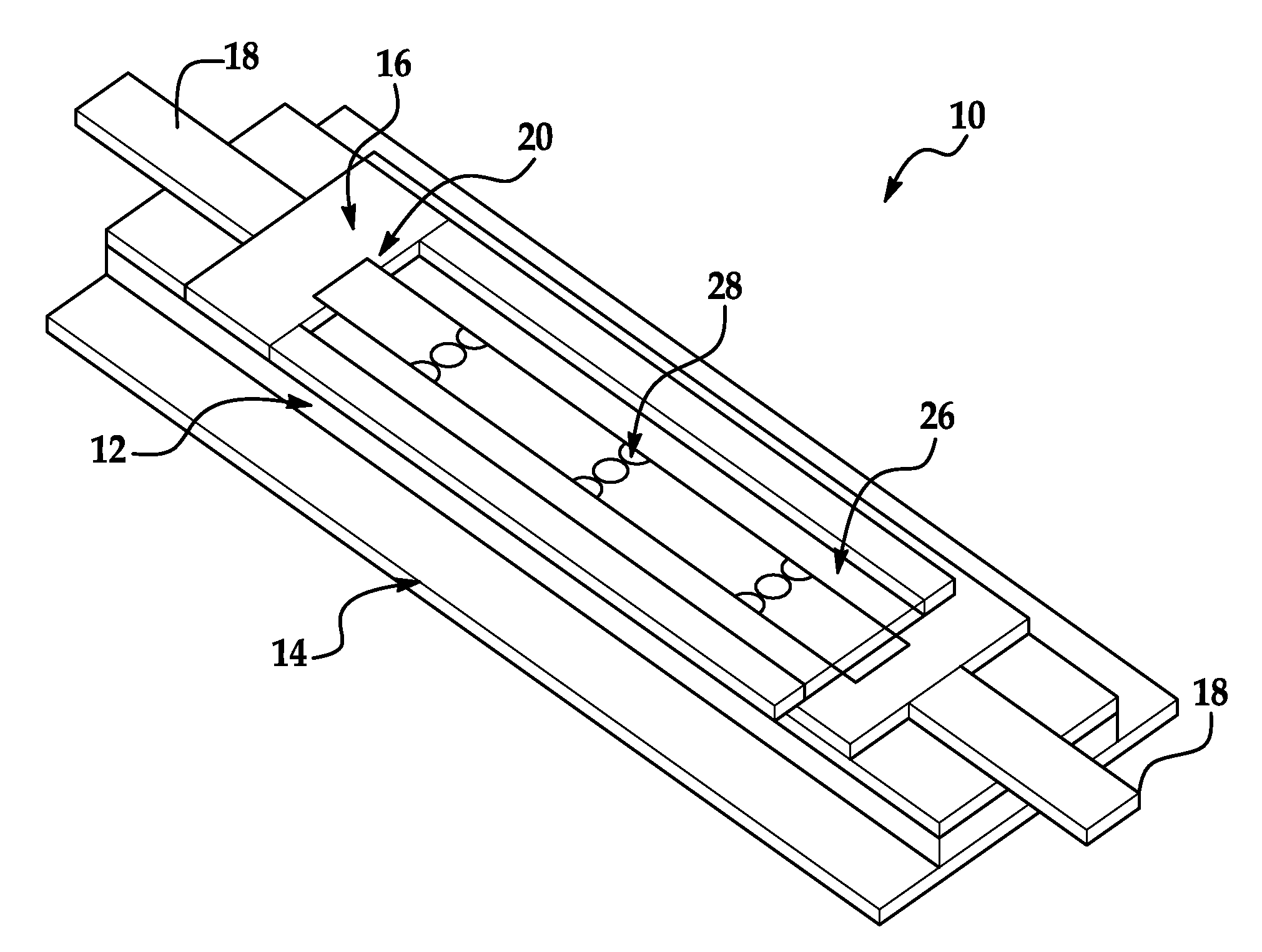
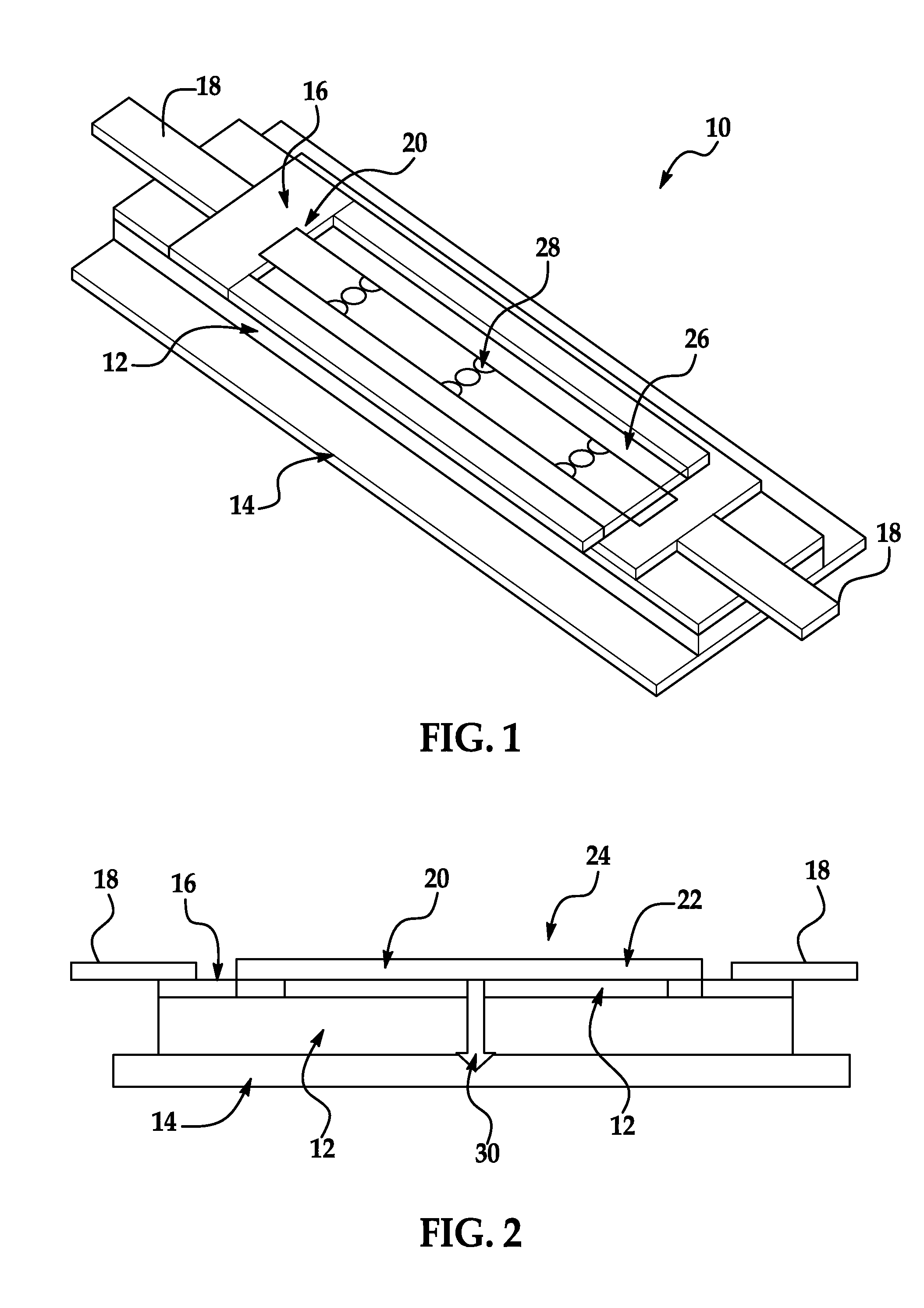
[0010]Referring now to the figures, a non-limiting embodiment of a fuse assembly according to the invention is shown at 10. Although the assembly 10 is disclosed herein as being implemented for a high-power motor controller for electrical-power generation / starting of an electric system of an aircraft, it should be appreciated that the assembly 10 can be implemented for any suitable type of motor controller. It should be appreciated also that the assembly 10 can be implemented for any suitable type of controller or even device.

[0011]As shown in the figures, the assembly 10 includes a base 12. In an aspect of the embodiment, the base 12 is made of ceramic. A coefficient of thermal expansion (CTE) of the base 12 can be about 20-22 micrometer / m-Deg C. Toward that end, the ceramic can be alumina (Al2O3) or boron nitride (BN).

[0012]The assembly 10 includes further a base plate 14 to which the base 12 is, in turn, attached. In an aspect, the base plate 14 is made of copper (Cu) and bonded ...


PUM


Abstract

A fuse assembly of a motor controller is provided. The fuse assembly includes a base, a base plate to which the base is attached, a lead frame that is attached to the base, at least one lead that is attached to the lead frame, and a fuse element attached to the base and covered with a fusible material. Heat is generated in the fuse element by a high flow of current carried by the assembly. The heat is operatively transferred through the assembly by direct conduction to the base and then base plate. The assembly sufficiently transfers heat to reduce rise in temperature of and properly cool the assembly. An operating temperature of the assembly is reduced to minimize or prevent damage thereto. The assembly has increased thermal-fatigue life and minimizes thermal-fatigue damage to the assembly during temperature cycling in an aircraft. Thermal stress of the assembly is minimized.

Description

BACKGROUND OF INVENTION[0001]This invention relates, generally, to a motor controller and, more specifically, to a fuse assembly of a high-power motor controller for electrical-power generation / starting of an electric system of an aircraft.[0002]A fuse assembly carrying a high flow of current (for example, about 26 A) is typically used in a motor controller. Such flow can cause generation of heat. In an exemplary assembly, an outer shell is pressed onto the assembly, and the assembly includes a fuse element that is fully encapsulated within a hard, rigid, compact, “sand-like” material. Sections of the fuse element are retained within one end of the assembly. The material does not fall loosely out of the assembly and restricts movement of the fuse element from thermal expansion. Heat is transferred from ends of the assembly.[0003]If the assembly is not properly cooled, the heat can cause damage to and failure of the assembly and / or a fuse link thereof. Also, temperature cycling in an...

Claims


Application Information

Patent Timeline
IPC IPC(8): H01H85/48
CPCH01H85/48H01H69/022H01H85/0241H01H85/046H01H85/10H01H85/47
Inventor PAL, DEBABRATA
Owner HAMILTON SUNDSTRAND CORP
Why Eureka
Try Eureka