

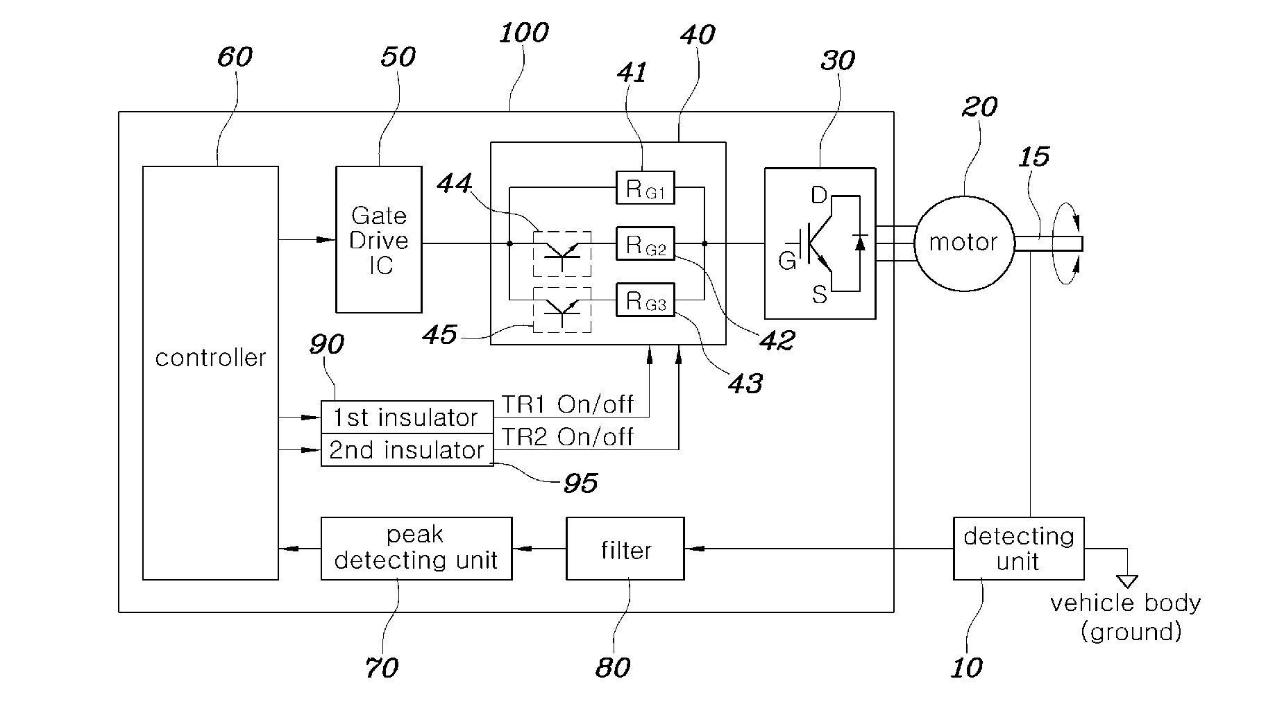
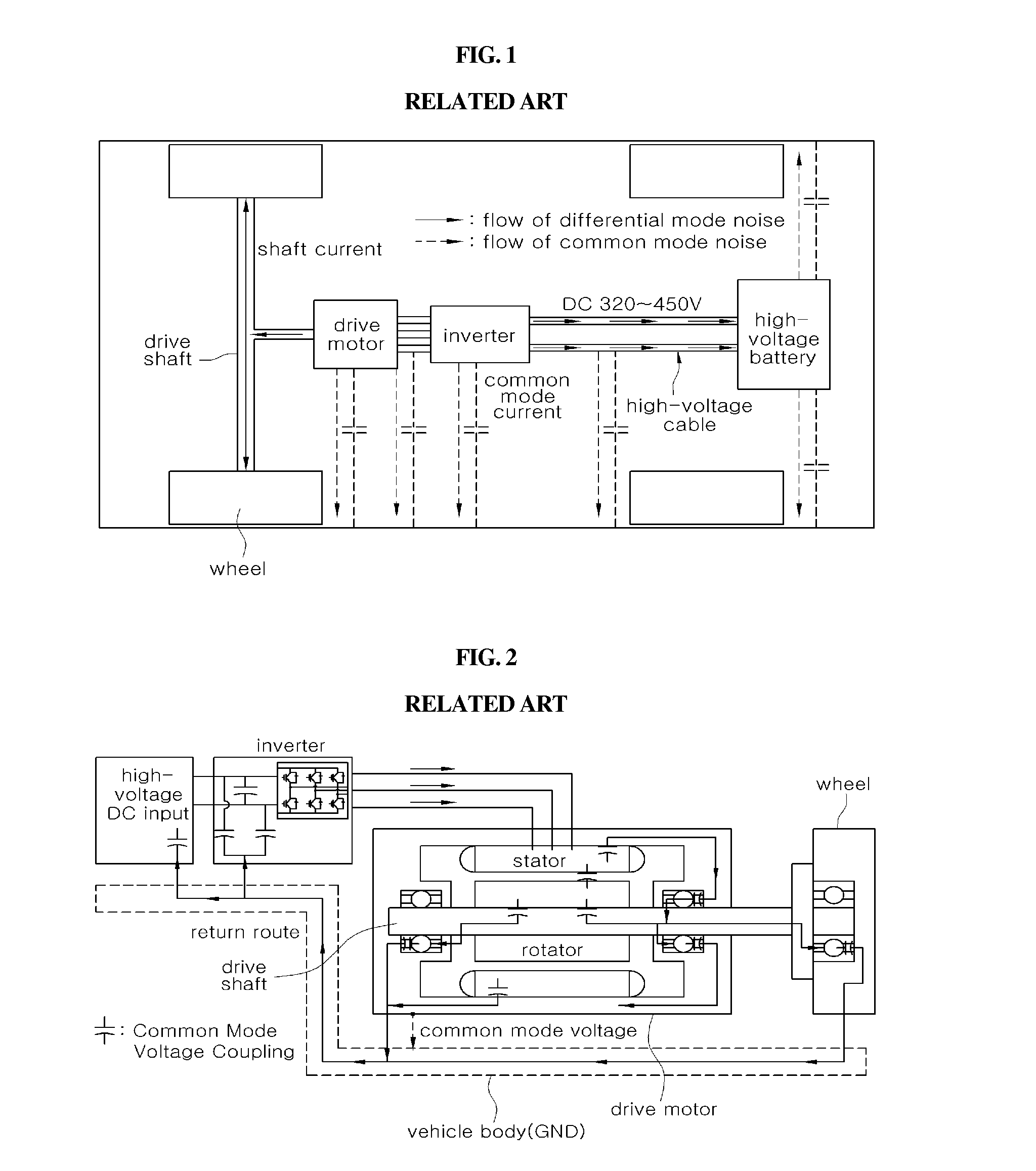
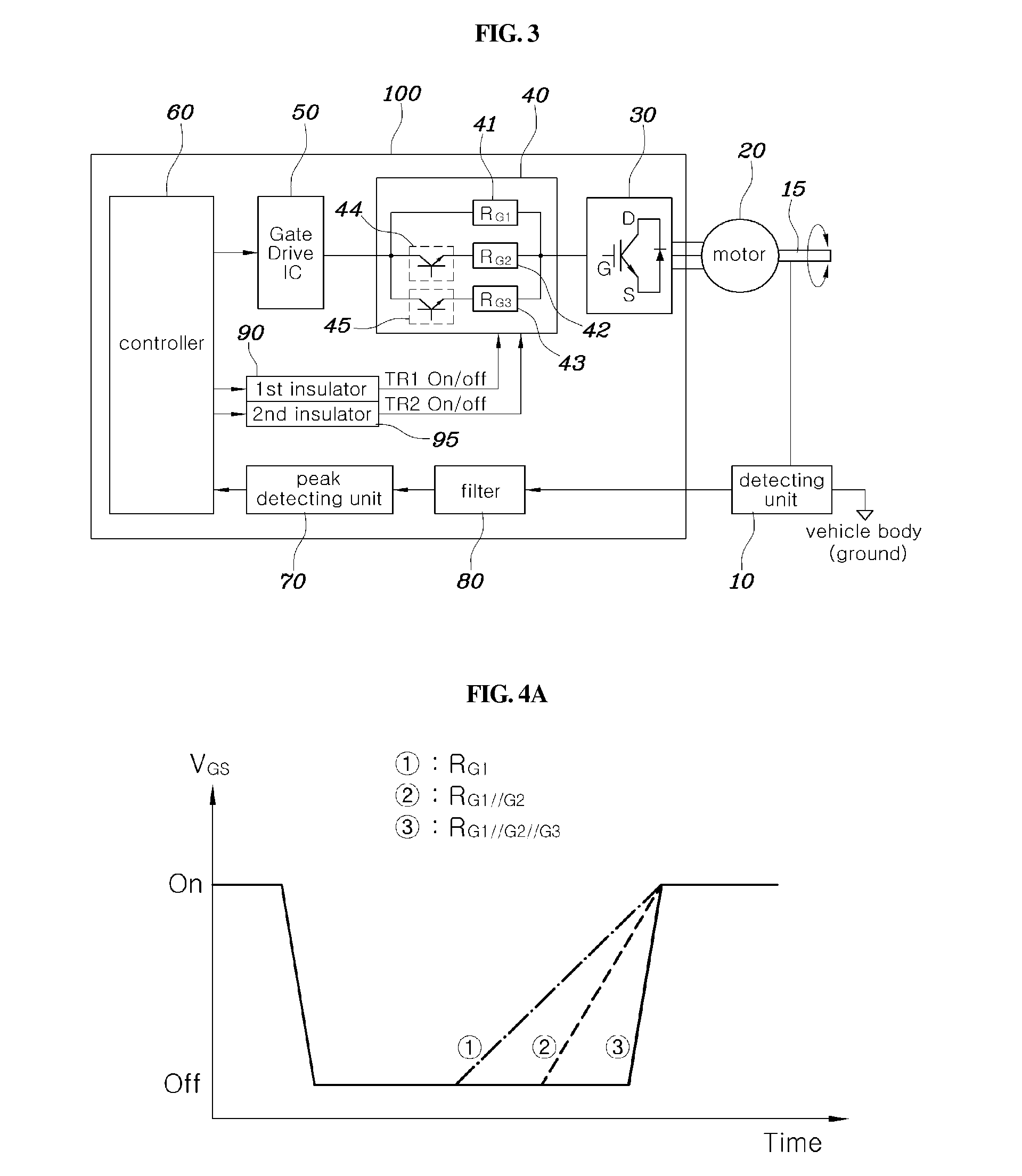
Apparatus and method for reducing common mode voltage
a common mode voltage and apparatus technology, applied in the direction of dc-ac conversion without reversal, motor/generator/converter stopper, dynamo-electric converter control, etc., can solve the problems of lowering the radio reception performance of the vehicle, poor driving force transmission, and harm to the controllers within the vehicle, so as to reduce the common mode voltage and increase the gate resistance
- Summary
- Abstract
- Description
- Claims
- Application Information
AI Technical Summary
Benefits of technology
Problems solved by technology
Method used
Image

Examples
Embodiment Construction
[0024]It is understood that the term “vehicle” or “vehicular” or other similar term as used herein is inclusive of motor vehicles in general such as passenger automobiles including sports utility vehicles (SUV), buses, trucks, various commercial vehicles, watercraft including a variety of boats and ships, aircraft, and the like, and includes hybrid vehicles, electric vehicles, plug-in hybrid electric vehicles, hydrogen-powered vehicles and other alternative fuel vehicles (e.g. fuels derived from resources other than petroleum). As referred to herein, a hybrid vehicle is a vehicle that has two or more sources of power, for example both gasoline-powered and electric-powered vehicles.
[0025]Although exemplary embodiment is described as using a plurality of units to perform the exemplary process, it is understood that the exemplary processes may also be performed by one or plurality of modules. Additionally, it is understood that the term controller / control unit refers to a hardware devi...
PUM
 Abstract
Description
Claims
Application Information