Urea water supply system

a technology of urea water supply and water supply system, which is applied in the direction of mechanical equipment, machines/engines, exhaust treatment electric control, etc., can solve problems such as failure in urea water supply, and achieve the effect of suppressing the occurrence of failur

Active Publication Date: 2015-12-17
TOYOTA JIDOSHA KK
View PDF8 Cites 20 Cited by
  • Summary
  • Abstract
  • Description
  • Claims
  • Application Information

AI Technical Summary

Benefits of technology

[0031]The above aspects of the invention suppress the occurrence of a failure in supply of urea water as much as possible in suck-back control of urea water in two supply paths in a pump share-type urea water supply system with two supply valves and two supply paths connecting with the respective supply valves.

Problems solved by technology

More specifically, the different capacities of the supply paths may cause a failure in supply of urea water (hereinafter may be simply referred to as “failure in supply”), for example, suck-back behavior causing urea water to remain in one of the supply paths.

Method used


Image

  • Urea water supply system
  • Urea water supply system
  • Urea water supply system

Examples


first embodiment

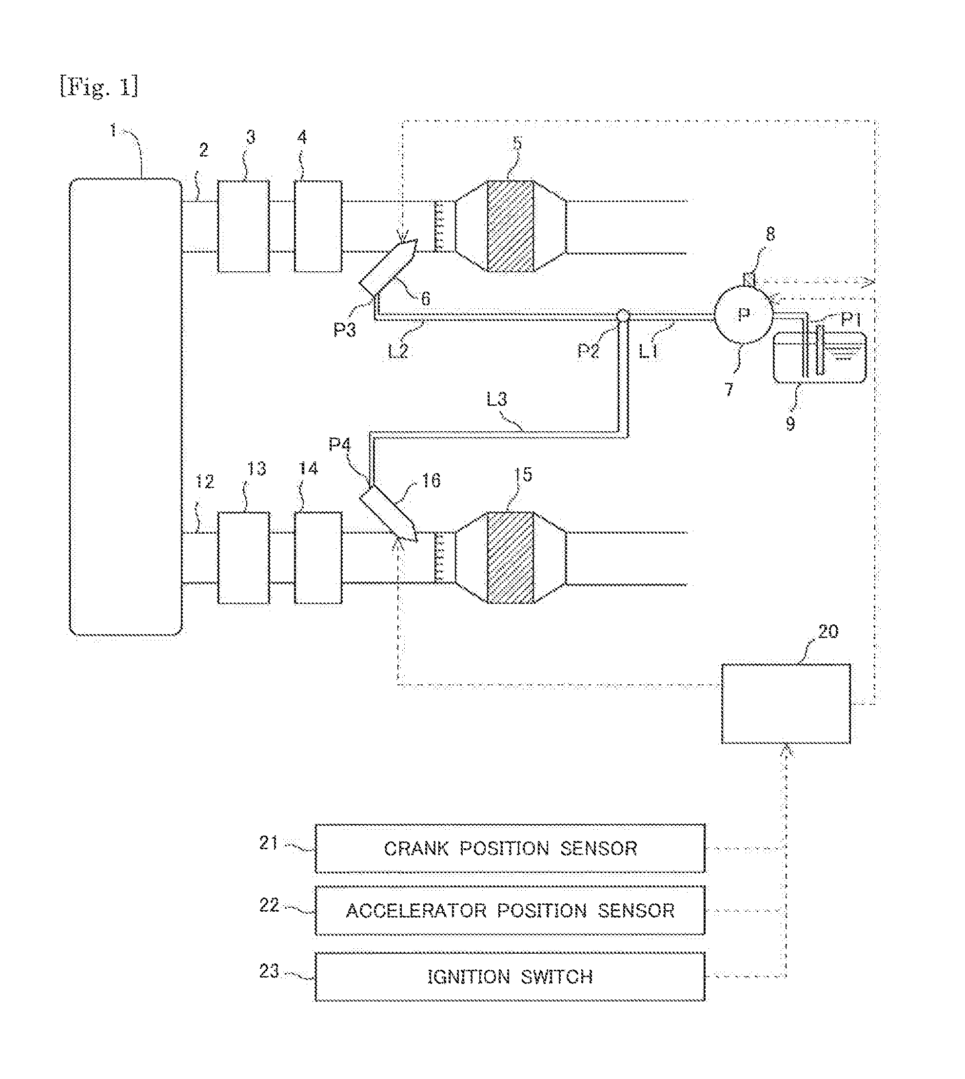
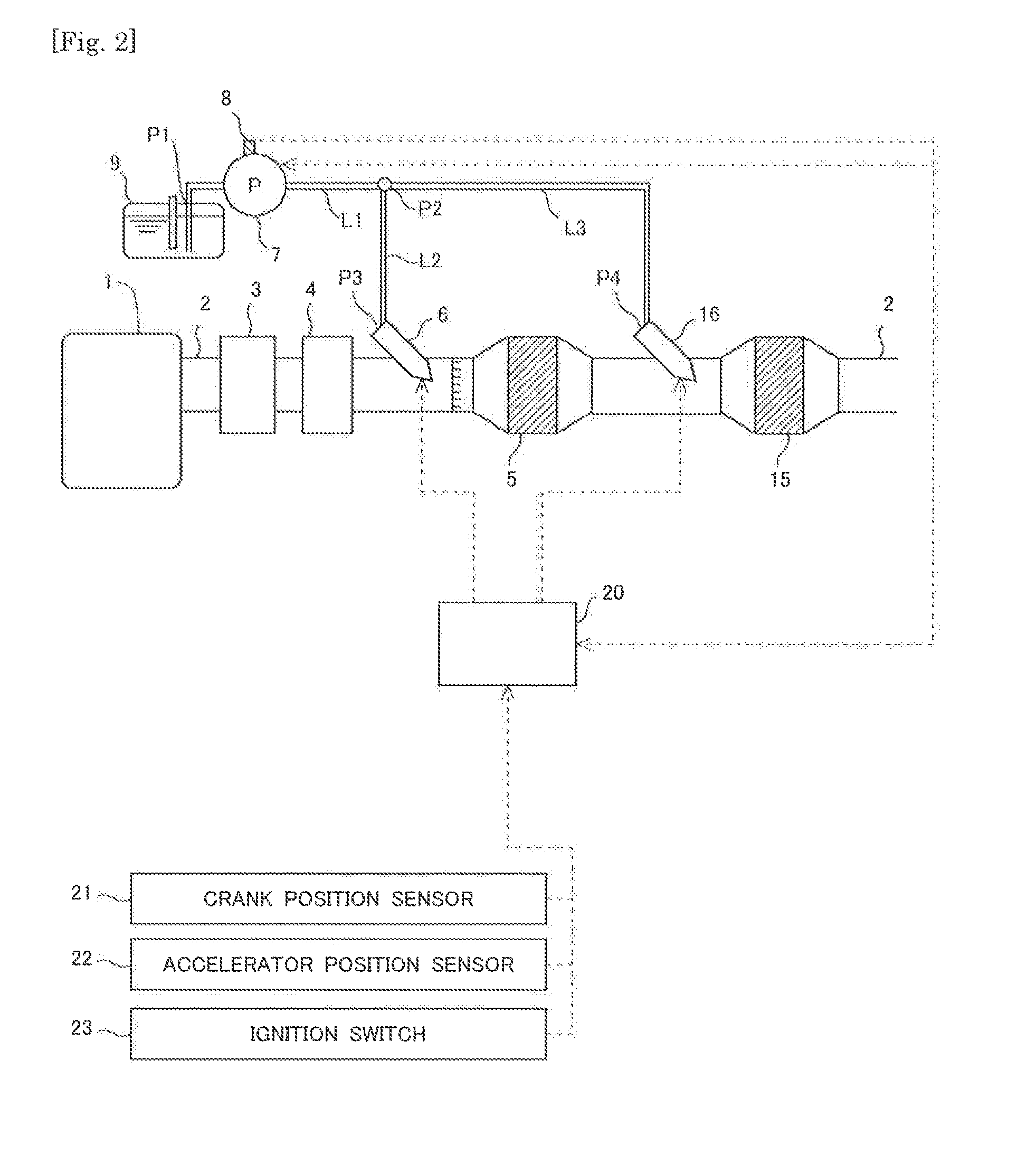
[0043]The following describes the schematic configurations of a urea water supply system (hereinafter may simply be referred to as “system”) and an exhaust emission control device of an internal combustion engine which the system is applied to, with reference to FIGS. 1 and 2. An internal combustion engine 1 shown in FIG. 1 is a diesel engine for driving a vehicle. The internal combustion engine of the invention is, however, not limited to the diesel engine but may be a gasoline engine or the like. The urea water supply system of the invention is configured to supply urea water to supply valves that are arranged to supply ammonium as a reducing agent to two NOx catalysts provided in an exhaust passage of the internal combustion engine 1. Exhaust emission control devices of FIGS. 1 and 2 are illustrated as examples of the exhaust emission control device of the internal combustion engine which the system is applied to and are not at all intended to limit the application of the inventi...

second embodiment

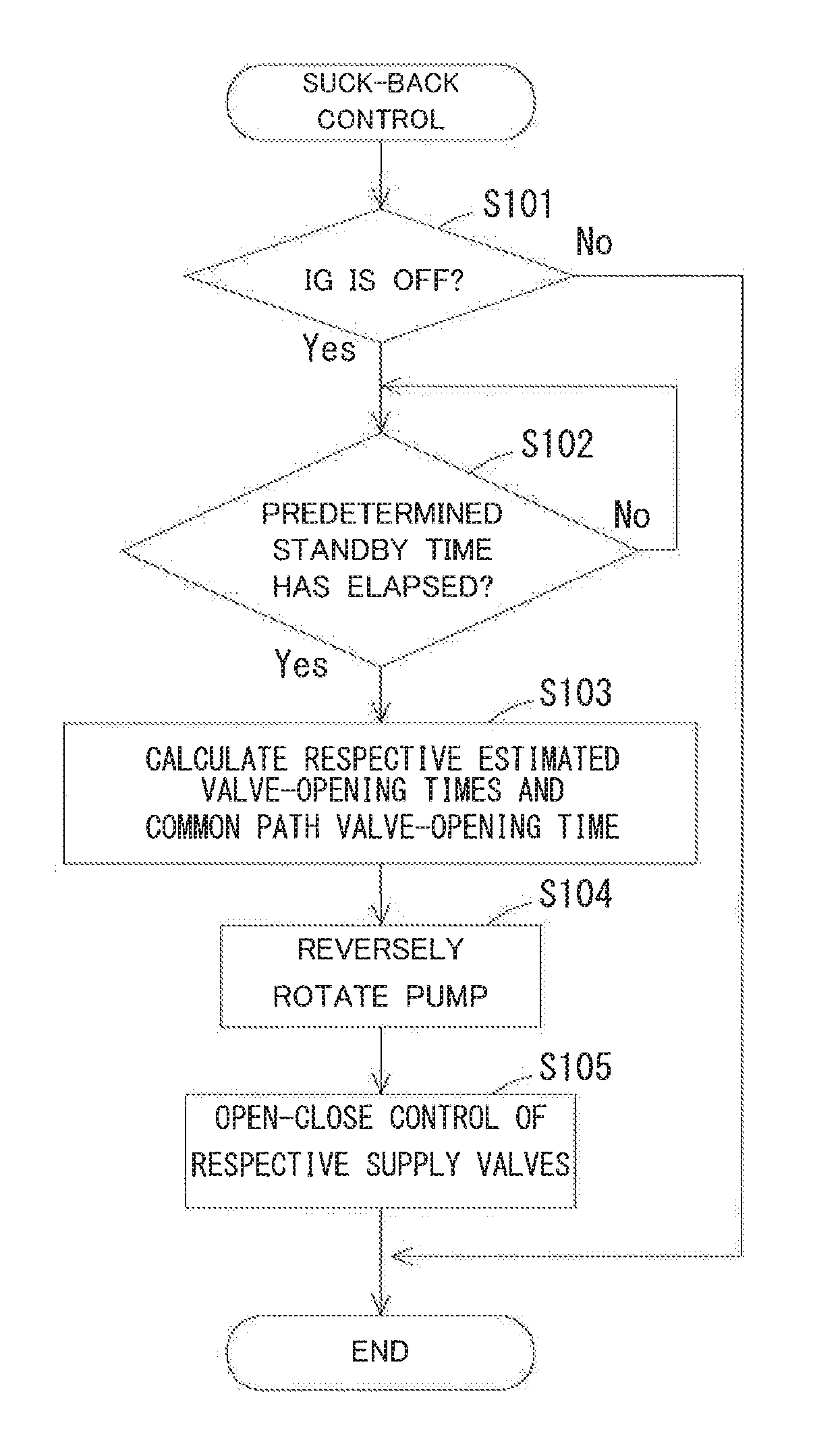
[0084]The following describes a second embodiment with regard to open-close control of the respective supply valves in suck-back control of urea water with reference to FIG. 7. The suck-back control shown in FIG. 7 is performed by the ECU 20 like the suck-back control shown in FIG. 3. The like steps in the suck-back control of FIG. 7 that are substantially similar to the steps in the suck-back control of FIG. 3 are expressed by the like step numbers and are not specifically described here. In this embodiment, it is assumed that the open-close control in the first pattern is performed as the open-close control of the respective supply valves at S105.

[0085]In this embodiment, after the processing of S105, the flow performs a clogging determination process with regard to clogging in the first supply valve 6 at S201. According to this embodiment, like the first pattern, the first estimated valve-opening time Tov1 is set to be shorter than the second estimated valve-opening time Tov2 by ...


PUM


Abstract

An object is to suppress the occurrence of a failure in supply of urea water as much as possible in suck-back control of urea water in a pump share-type urea water supply system with two supply valves. In the pump share-type urea water supply system with a first supply valve and a second supply valve, a urea water tank is connected with the respective supply valves by a urea water supply path. The urea water supply path includes a first supply path for the first supply valve and a second supply path for the second supply valve. The second supply path has a larger capacity than the capacity of the first supply path by a predetermined volume. The suck-back control of urea water controls opening and closing of the respective supply valves such that a first estimated valve-opening time that is a valve-opening time of the first supply valve estimated to be required for suck-back control in the first supply valve and in the first supply path is shorter than a second estimated valve-opening time that is a valve-opening time of the second supply valve estimated to be required for suck-back control in the second supply valve and in the second supply path by at least a first control time corresponding to the predetermined volume.

Description

CROSS REFERENCE TO RELATED APPLICATIONS[0001]This application claims priority to Japanese Patent Application No. 2014-121579 filed on Jun. 12, 2014 and Japanese Patent Application No. 2015-105699 filed on May 25, 2015, the entire contents of which are incorporated by reference herein.BACKGROUND[0002]1. Field of Invention[0003]The present invention relates to a urea water supply system that supplies urea water to the exhaust emission for reduction of NOx using a selective reduction NOx catalyst provided in an exhaust passage of an internal combustion engine.[0004]2. Description of the Related Art[0005]A known configuration of an exhaust emission control device provides a selective reduction NOx catalyst (hereinafter simply referred to as “NOx catalyst”) that reduces NOx included in the exhaust emission discharged from an internal combustion engine by using ammonia as a reducing agent. A supply valve is provided in the upstream of the NOx catalyst to supply urea water to the exhaust e...

Claims


Application Information

Patent Timeline
Patent Type & Authority Applications(United States)
IPC IPC(8): F01N11/00F01N3/28F01N3/20
CPCF01N11/00F01N3/2896F01N3/208F01N3/2066F01N2610/02F01N2610/144F01N2610/146F01N2610/1486F01N2610/1493F01N2900/1808F01N2900/1822F01N13/0093F01N13/011Y02T10/12
Inventor MATSUO, JUNICHIOHASHI, NOBUMOTOMIKAMI, AKIRATAKADA, KEISHINAKAYAMA, SHIGEKI
Owner TOYOTA JIDOSHA KK
Why Eureka
Try Eureka