
Method for Creating Switch Reluctance Motor Memory Sensor Model

a technology of switch reluctance and memory sensor, which is applied in the direction of electric/magnetic computing, instruments, analogue processes for specific applications, etc., can solve the problems of conflict between operation cost and instantaneity of system, large optimization design error, etc., and achieve the effect of improving system dynamic and static performan

Active Publication Date: 2015-12-17
CHINA UNIV OF MINING & TECH
View PDF0 Cites 3 Cited by
  • Summary
  • Abstract
  • Description
  • Claims
  • Application Information

AI Technical Summary

Benefits of technology

The present invention is a memory sensor circuit for a switch reluctance motor that uses a hardware circuit to create a model for the motor by using a passive two-end element of a memory resistor. This circuit has low hardware cost and is able to simulate and control the motor system. The circuit can also optimize design, analyze performance, and evaluate control strategy. The invention provides a simplified and accurate model for the switch reluctance motor that can be used for simulation and control.

Problems solved by technology

Therefore, the linear model of the switch reluctance motor results in a big error in the optimization design, the quantitative analysis of the static and dynamic performance, the evaluation of control strategy and the like of the motor.
Phase inductance nonlinear modelling of the switch reluctance motor is the key for creating an accurate nonlinear model for the switch reluctance motor, however, it is difficult to utilize a traditional modelling method for a motor in the modelling of a switch reluctance motor.
Phase inductance digitize nonlinear modelling for the switch reluctance motor requires a simulator and a controller to have great computing power in simulation and actual control, causing a conflict between operation cost and instantaneity of a system.

Method used


Image

  • Method for Creating Switch Reluctance Motor Memory Sensor Model
  • Method for Creating Switch Reluctance Motor Memory Sensor Model
  • Method for Creating Switch Reluctance Motor Memory Sensor Model

Examples


Embodiment Construction

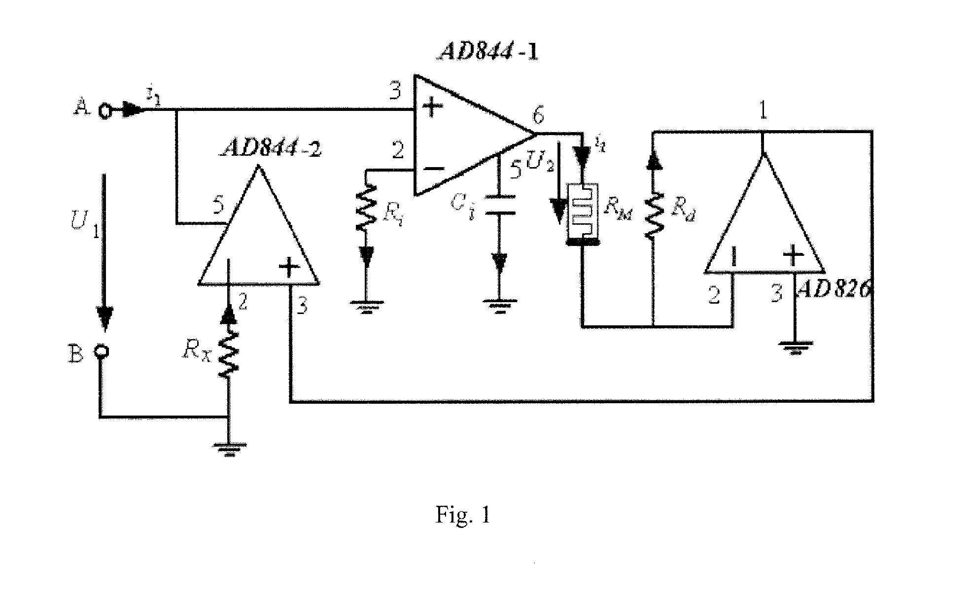
[0008]One embodiment of the present invention is further described below in conjunction with the drawings:

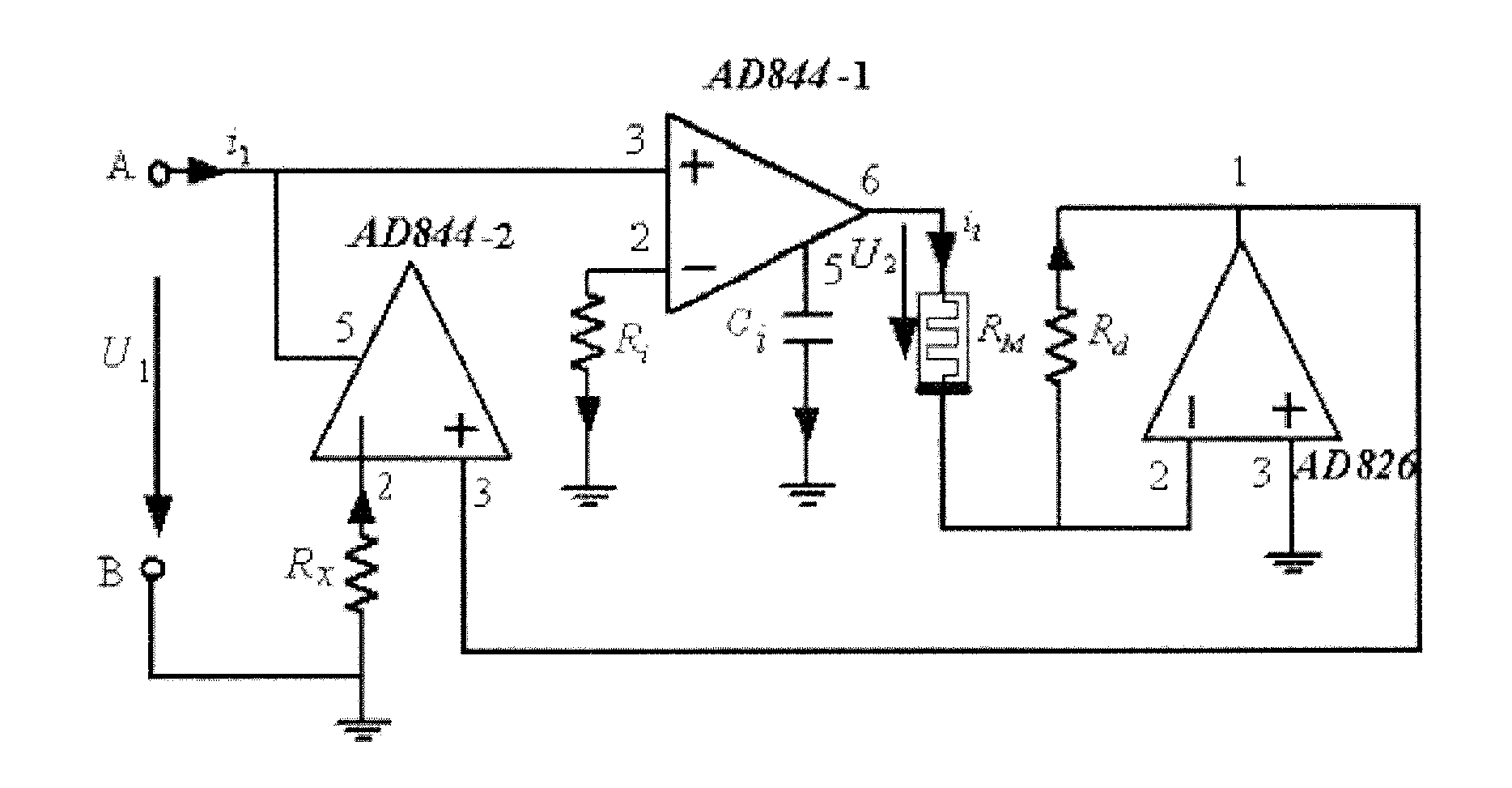
[0009]As shown in FIG. 1, the modelling method for a memory sensor model of a switch reluctance motor in the present invention is as follows:[0010]a) two current conveyors AD844, an operational amplifier AD826 and a memory resistor are utilized, wherein the terminal voltage of the input ports A-B of the memory sensor is U1, and the current flowing into the memory sensor from the input port A thereof is ii;[0011]b) the input port A of the memory sensor is connected with an in-phase input port 3 of the current conveyor AD844-1 that is in turn connected with a port 5 of the current conveyor AD844-2; an out-phase input port 2 of the current conveyor AD844-1 is connected with one end of a resistor Ri, the other end of which is connected with the ground; the port 5 of the current conveyor AD844-1 is connected with one end of a capacitor Ci, the other end of which is connected with the...


PUM


Abstract

A method for creating a switch reluctance motor memory sensor model. A switch reluctance motor memory sensor circuit model is formed by two current transmitters AD844, an operational amplifier AD826, a memristor, a capacitor, and three resistors. The method for creating a switch reluctance motor memory sensor model enables physical phenomena in a simulation system to be similar to an actual switch reluctance motor system, and is beneficial for direct mathematical simulation of a switch reluctance motor system. The method is simple, can improve static and dynamic performance of a system, and achieves real-time simulation and real-time control of the switch reluctance motor system.

Description

I. TECHNICAL FIELD[0001]The present invention relates to a modelling method for a switch reluctance motor memory sensor model, which is especially suitable for switch reluctance motors with different phases.II. BACKGROUND ART[0002]A linear model of the switch reluctance motor ignores nonlinear factors such as magnetic saturation, such that the phase inductance of the switch reluctance motor is only associated with the positional angle of the rotor thereof, but not with the magnitude of phase current. Therefore, the linear model of the switch reluctance motor results in a big error in the optimization design, the quantitative analysis of the static and dynamic performance, the evaluation of control strategy and the like of the motor. As the switch reluctance motor itself has local magnetic saturation and a nonlinear magnetic circuit, and the power converter thereof is in a switch mode and has a nonlinear circuit topology, the phase inductance of the switch reluctance motor has a nonl...

Claims


Application Information

Patent Timeline
Patent Type & Authority Applications(United States)
IPC IPC(8): G06F17/50H02K11/00H02P25/08
CPCG06F17/5036H02K11/001H02P25/08G06F30/367
Inventor CHEN, HAOLIANG, YAN
Owner CHINA UNIV OF MINING & TECH
Learn More