

Stage apparatus, lithography apparatus, and articles manufacturing method
- Summary
- Abstract
- Description
- Claims
- Application Information
AI Technical Summary
Benefits of technology
Problems solved by technology
Method used
Image

Examples
first embodiment
Configuration of Drawing Apparatus
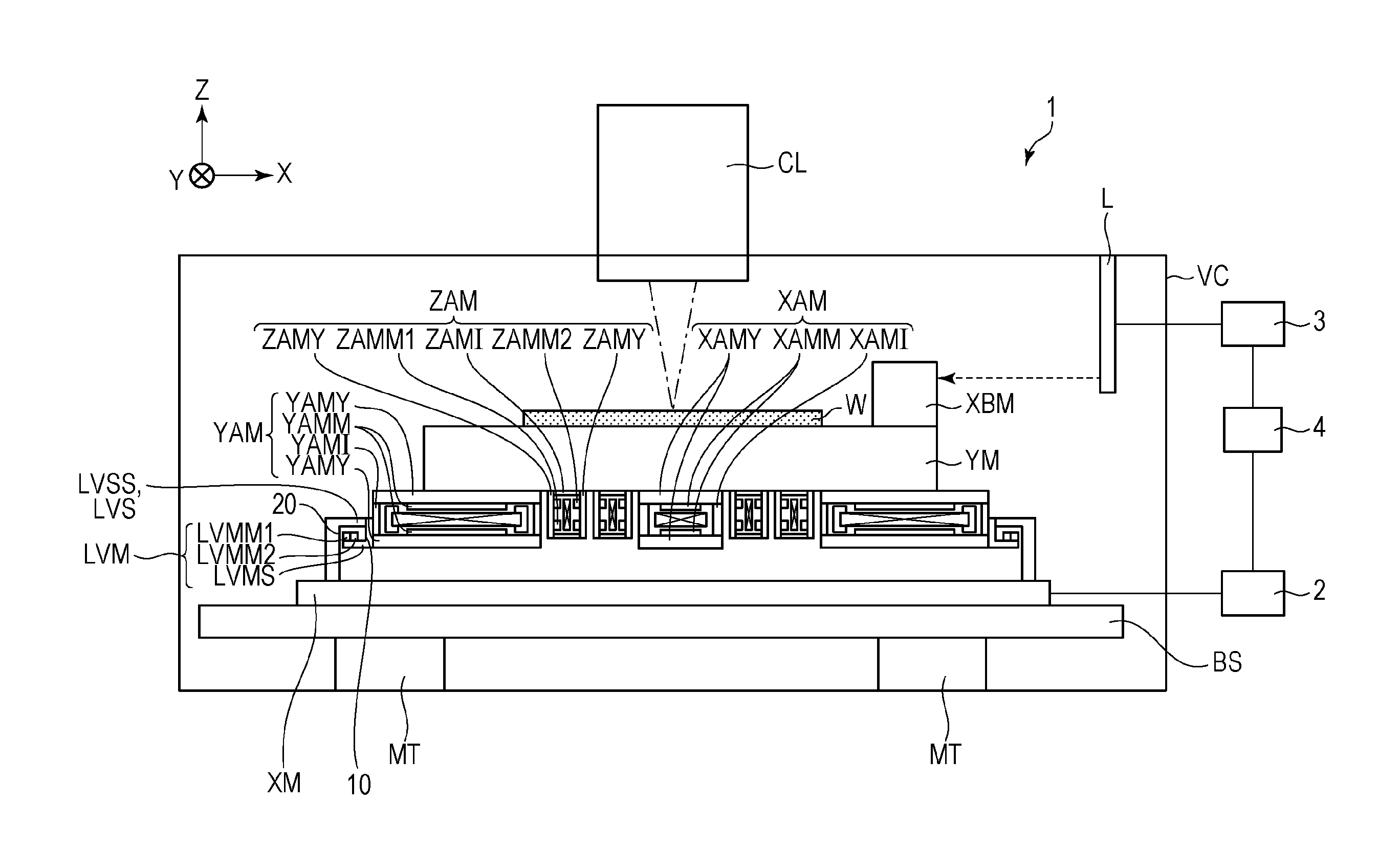
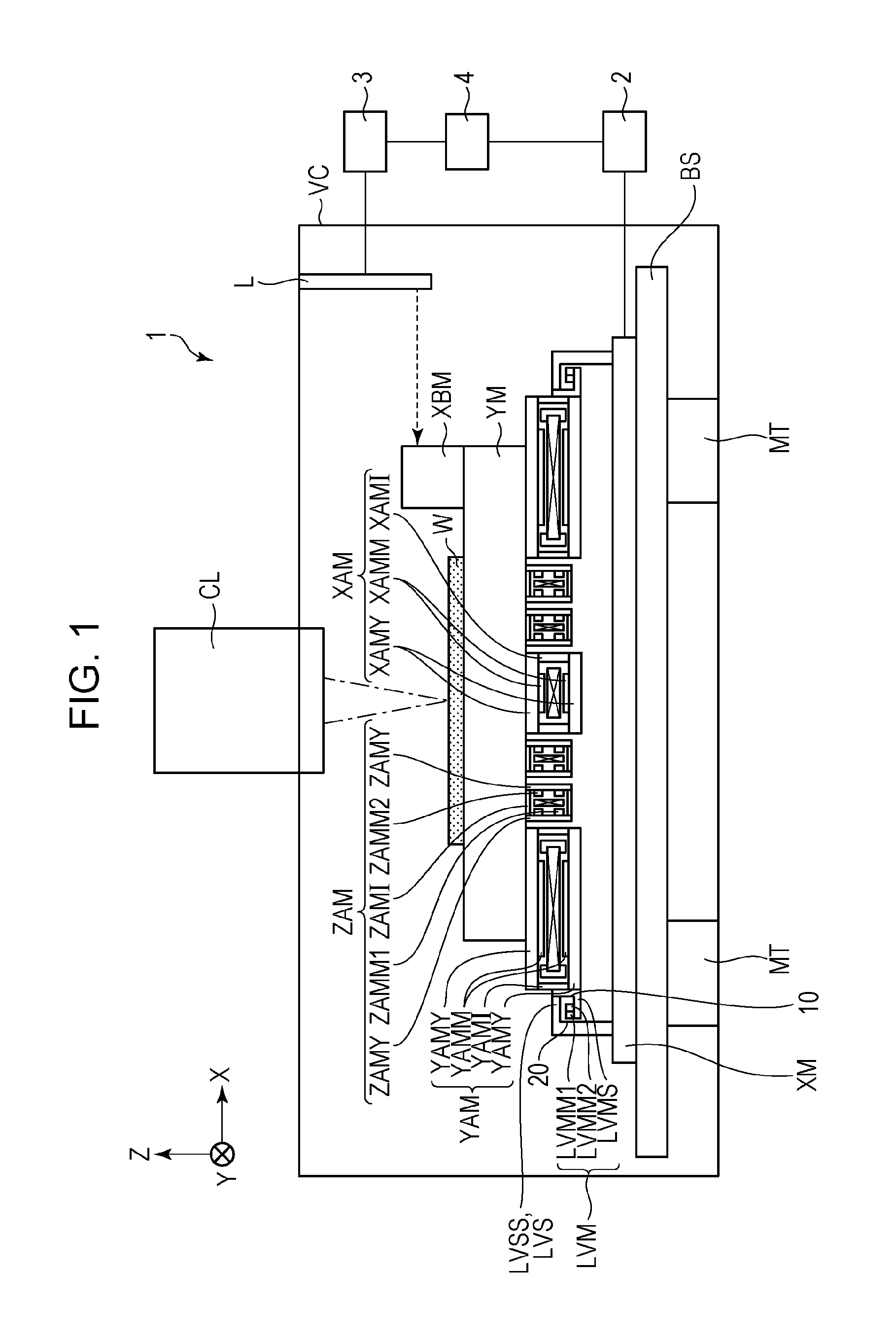
[0014]A stage apparatus of a first embodiment will be described with reference to FIG. 1. FIG. 1 is a front view of a drawing apparatus (lithography apparatus) 1 configured to form a pattern by irradiating a wafer (substrate) W having a resist applied thereto with an electron beam. A lens barrel CL includes an electron source (not illustrated) configured to generate the electron beam and an electronic optical system (not illustrated) configured to converge the electron beam emitted by the electron beam source on the wafer W. In addition, the lens barrel CL is installed so as to penetrate a vacuum chamber VC, and an interior of the vacuum chamber VC and an interior of the lens barrel CL are maintained in a vacuum atmosphere by using a vacuum pump (not illustrated).
[0015]A bottom portion in the vacuum chamber VC includes a platen BS as a base and a mount MT configured to support the platen BS and reduce external vibrations transmitted to the platen BS...
second embodiment
[0040]FIG. 3 illustrates a configuration of a fixed unit LVS and a movable unit LVM of a stage apparatus according to a second embodiment. The second embodiment is different from the first embodiment in that a magnetic material LVSS has a blocking surface 20 so as to face not only a side surface of a permanent magnet LVMM2, but also face a side surface of a permanent magnet LVMM1.
[0041]In this embodiment as well, the side surfaces of the permanent magnets LVMM1 and LVMM2 in the Y-axis direction are covered by combining a blocking surface 10 and the blocking surface 20 that a reduction of the magnetic field directed in the horizontal direction is achieved. In addition, in the case of this embodiment, since much of the magnetic field leaking from the permanent magnet LVMM1 and the permanent magnet LVMM2 in a −X direction is absorbed by a magnetic material LVSS having the blocking surface 20, leakage of the magnetic field in the −X direction rarely occurs.
[0042]Since the magnetic field...
third embodiment
[0043]FIG. 4 illustrates a configuration of a fixed unit LVS and a movable unit LVM of a stage apparatus according to a third embodiment. A magnetic material LVMS of the movable unit LVM includes a convex portion 30 so as to have a blocking surface 10 which faces both side surfaces of permanent magnets LVMM1 and LVMM2.
[0044]The magnetic material LVMS of the fixed unit LVM includes the convex portion 30 so as to have a blocking surface 20 which overlaps partly with the blocking surface 10 in the −X direction when viewed from the permanent magnet LVMM1. In the same manner, the convex portion 30 is formed so as to have the blocking surface 20 which partly overlaps with the blocking surface 10 also in the +X direction when viewed from the permanent magnet LVMM1. A supporting member LVSZ, which is a non-magnetic material, of the fixed unit LVS supports a magnetic material LVSS. A supporting member LVMZ, which is a non-magnetic material, of the movable unit LVM supports the magnetic mater...
PUM
 Abstract
Description
Claims
Application Information