
Liquid Supply Apparatus

a technology of liquid supply apparatus and liquid supply valve, which is applied in the direction of positive displacement liquid engine, fluid pressure control, instruments, etc., can solve the problems of limited flow rate, low flow rate, and high cost of flowmeter, so as to reduce the flow rate of fluid, reduce the pressure of fluid, and increase the flow rate or the pressure of fluid.

Inactive Publication Date: 2015-12-24
MATSUI MFG
View PDF0 Cites 10 Cited by
  • Summary
  • Abstract
  • Description
  • Claims
  • Application Information

AI Technical Summary

Benefits of technology

The liquid supply apparatus described in this patent allows for control of the flow rate, pressure, and temperature of a liquid. This is achieved through a medium control part that adjusts the frequency of the inverter, which is the main component of the apparatus. The control part can lower or raise the frequency of the inverter depending on the detected torque or pressure of the liquid. This allows for precise control of the liquid flow rate and pressure, improving the efficiency and accuracy of the liquid supply process.

Problems solved by technology

However, a flowmeter is extremely expensive and hence the flowmeter is seldom installed actually.
Thus, in practice, the actual flow rate of the liquid is not allowed to be recognized and hence the flow rate is restricted more than an appropriate extent by a manual valve.
Thus, in the conventional art, the flow rate of the pipeline was not allowed to be recognized.
Further, also the adjustment valve for adjusting the flow rate of the pipeline may be not provided.
However, according to the above-described configuration, even when the state of the load such as a mold tool varies, a situation is avoided that the pressure of the liquid becomes excessively high.
Thus, the bypass passage may be not provided.

Method used


Image

  • Liquid Supply Apparatus
  • Liquid Supply Apparatus
  • Liquid Supply Apparatus

Examples


Embodiment Construction

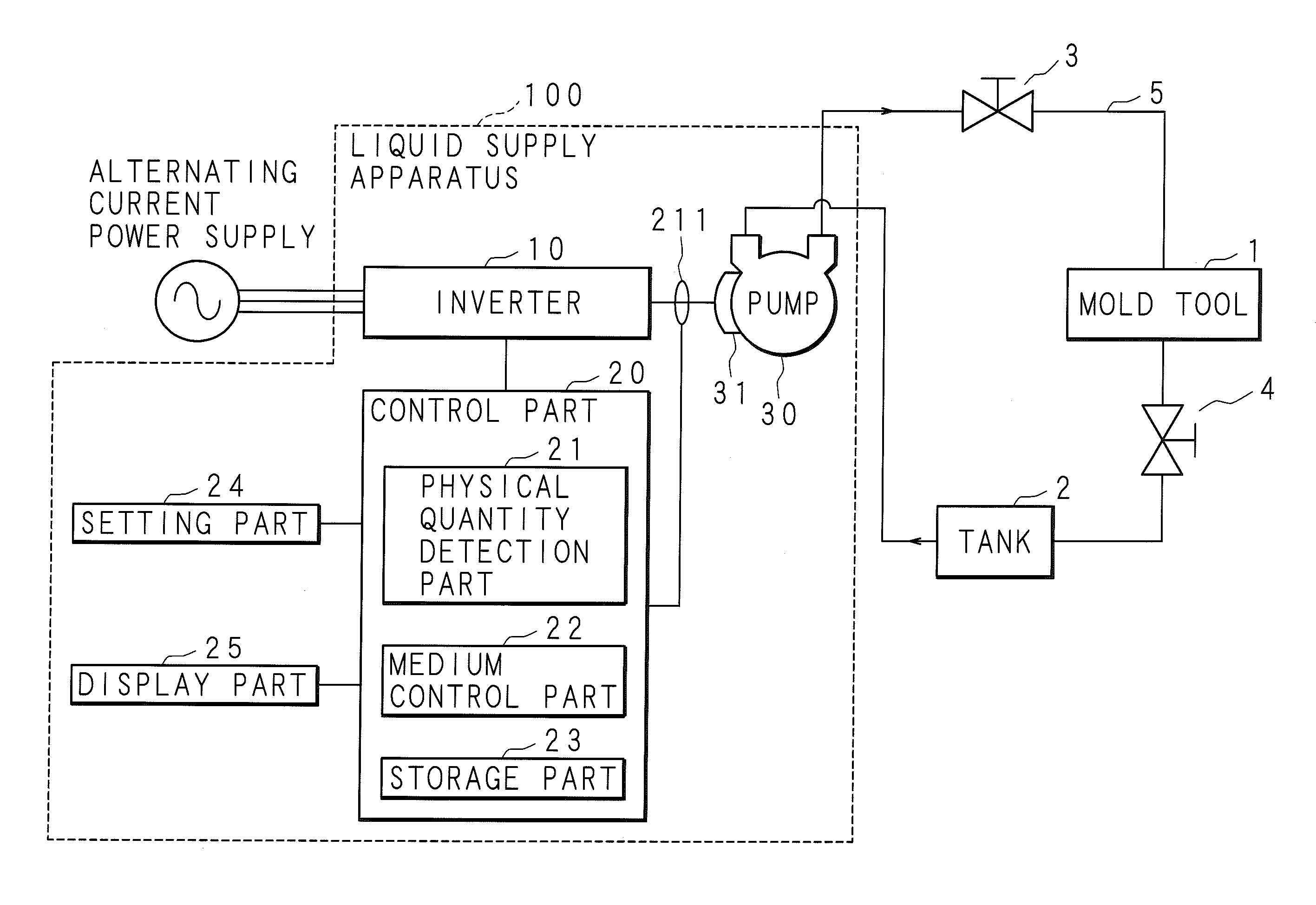
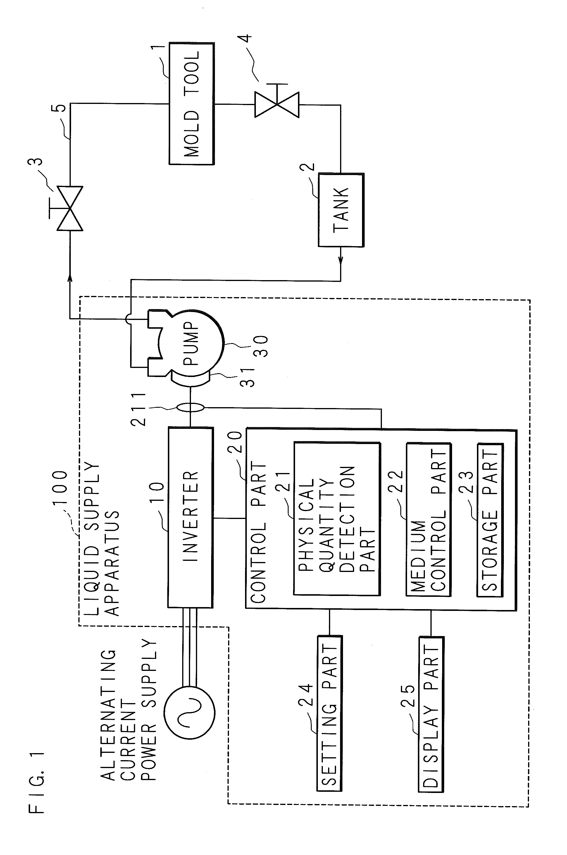
[0054]Hereinafter, the present invention is described below with reference to the drawings illustrating embodiments thereof. FIG. 1 is an explanation diagram illustrating an example of configuration of a liquid supply system including a liquid supply apparatus 100 of the present embodiment. As illustrated in FIG. 1, the liquid supply apparatus 100 includes an inverter 10, a control part 20, a pump 30, a setting part 24, a display part 25, and the like. The control part 20 includes a physical quantity detection part 21, a medium control part 22, a storage part 23 and the like. The pump 30 includes a motor 31 serving as an electric motor.

[0055]A pipe 5 for sending the liquid from the pump 30 to a mold tool 1 and a pipe 5 for returning the liquid from the mold tool 1 to the pump 30 are connected between the pump 30 and the mold tool 1 to which a liquid is supplied. A medium sending valve 3 is inserted in the pipe 5 for sending the liquid from the pump 30 to the mold tool 1. Further, a ...


PUM

PropertyMeasurementUnit
Pressureaaaaaaaaaa
Poweraaaaaaaaaa
Flow rateaaaaaaaaaa

Abstract

The liquid supply apparatus includes: an inverter converting the frequency of an alternating-current power supply; a pump including an electric motor driven by the inverter; a control part; and the like. The control part includes a physical quantity detection part, a medium control part, and the like. The physical quantity detection part detects a physical quantity concerning the output of the inverter. On the basis of the physical quantity detected by the physical quantity detection part, the medium control part controls at least one of the flow rate and the pressure of the liquid supplied by the pump.

Description

CROSS-REFERENCE TO RELATED APPLICATIONS[0001]This application is the national phase under 35 U.S.C. §371 of PCT[0002]International Application No. PCT / JP2013 / 055080 which has an International filing date of Feb. 27, 2013 and designated the United States of America.BACKGROUND[0003]The present invention relates to a liquid supply apparatus provided with an inverter converting a frequency of an alternating-current power supply and with a pump including an electric motor driven by the inverter, and thereby supplying a liquid by using the pump.DESCRIPTION OF RELATED ART[0004]In an injection molding machine performing injection molding of a molded article by using synthetic resin such as plastics, a mold tool is employed. The mold tool for injection molding includes: a cavity serving as a space part into which melted plastics is loaded; and a pipeline through which a liquid such as cooling water flows for the purpose of cooling and solidification of the melted plastics. Maintaining of the...

Claims


Application Information

Patent Timeline
IPC IPC(8): G05D7/06H02P27/06F04D13/06G05D16/20F04D1/00
CPCG05D7/0676G05D16/2066F04D1/00Y10T137/85986H02P27/06Y10T137/8326F04D13/06F04B49/065F04B49/08F04B2205/05F04B2205/09B29C45/76B29C2945/76033B29C2945/76334B29C2945/76498B29C2945/76545B29C2945/76782H02P23/009F04B17/03
Inventor HANAOKA, KAZUNARIYAMASHITA, SAIJISHIMIZU, MOTOHARU
Owner MATSUI MFG
Learn More