Magnetoelectric Pickup Element for Detecting Oscillating Magnetic Fields
a pickup element and magnetic field technology, applied in the direction of instruments, electrotrophonic instruments, etc., can solve the problem that the material choice is not always optimal, and achieve the effect of rich sound and high sensitiveness
- Summary
- Abstract
- Description
- Claims
- Application Information
AI Technical Summary
Benefits of technology
Problems solved by technology
Method used
Image

Examples
example 1
Preparation of Magnetoelectric Sensor Devices Having Different Magnetorestrictive Components
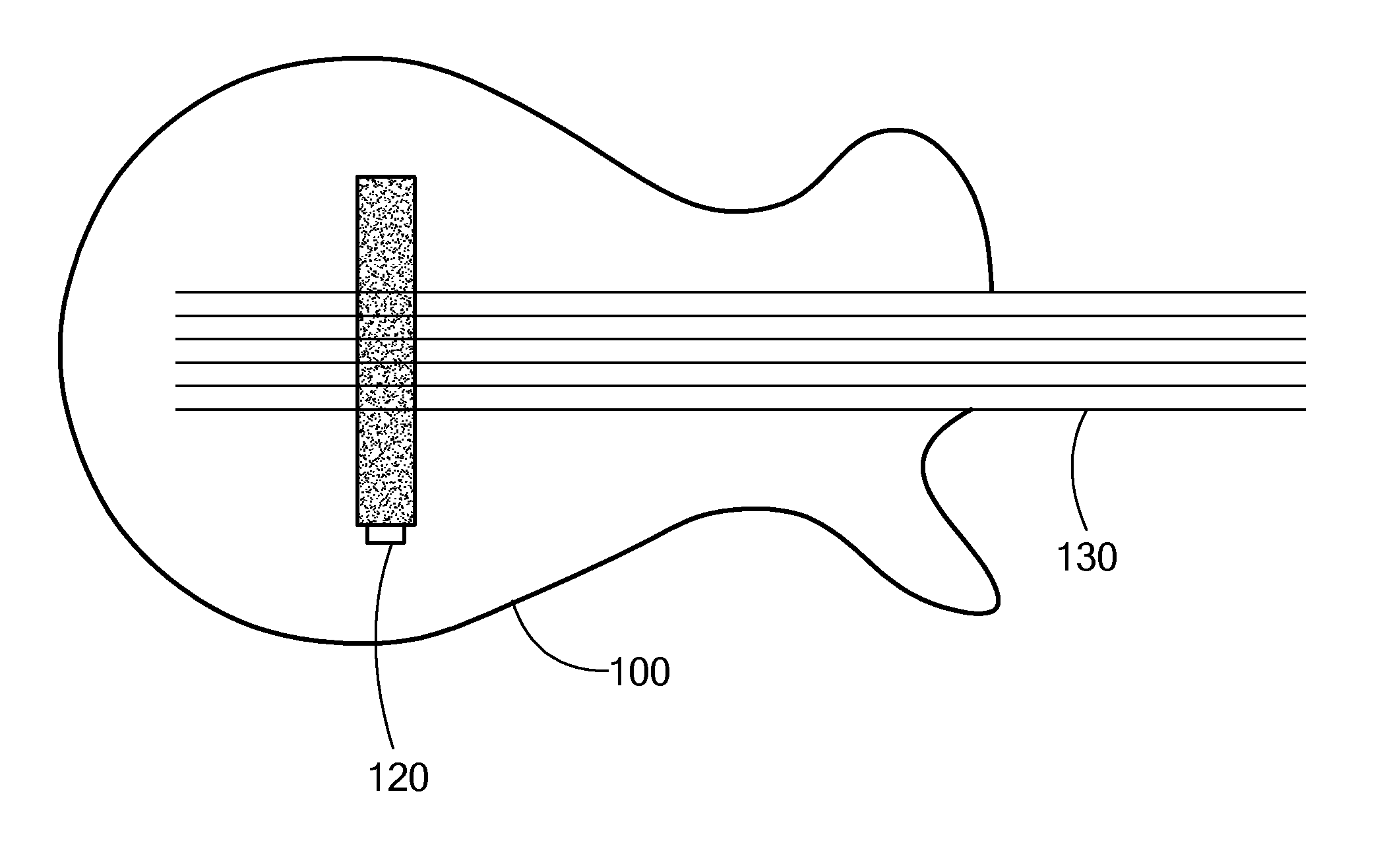
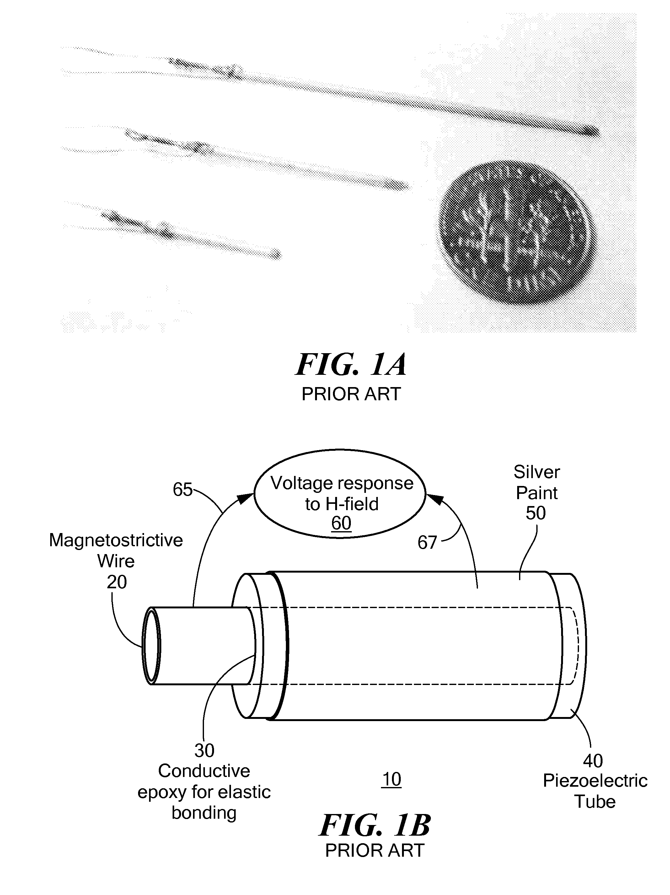
[0035]Three types of magnetoelectric wires galfenol (FG), iron-cobalt-vanadium (FC), and iron-nickel (FN) were used in the fabrication of three equal length magnetoelectric sensors. Each magnetostrictive wire had a diameter of 0.5 mm, and was coupled into a 5 cm long PZT tube having an inner diameter of 0.8 mm and outer diameter of 1 mm. The wire and tube were elastically bonded using a sintered silver-paste epoxy. Wire lengths of 7 cm were used to reduce strain clamping at opposite ends of the active interface, and to provide a contact point for inner electrode. The PZT tube was centered on each wire such that 1 cm of bare wire was exposed at either end of the sensor. Silver paint was applied to the surface of the PZT tube for use as an outer electrode. One copper lead was soldered onto the magnetostrictive wire and a second lead soldered onto the silver paint applied to the exterior of the ...
example 2
Voltage Detection Using Magnetoelectric Sensor Devices
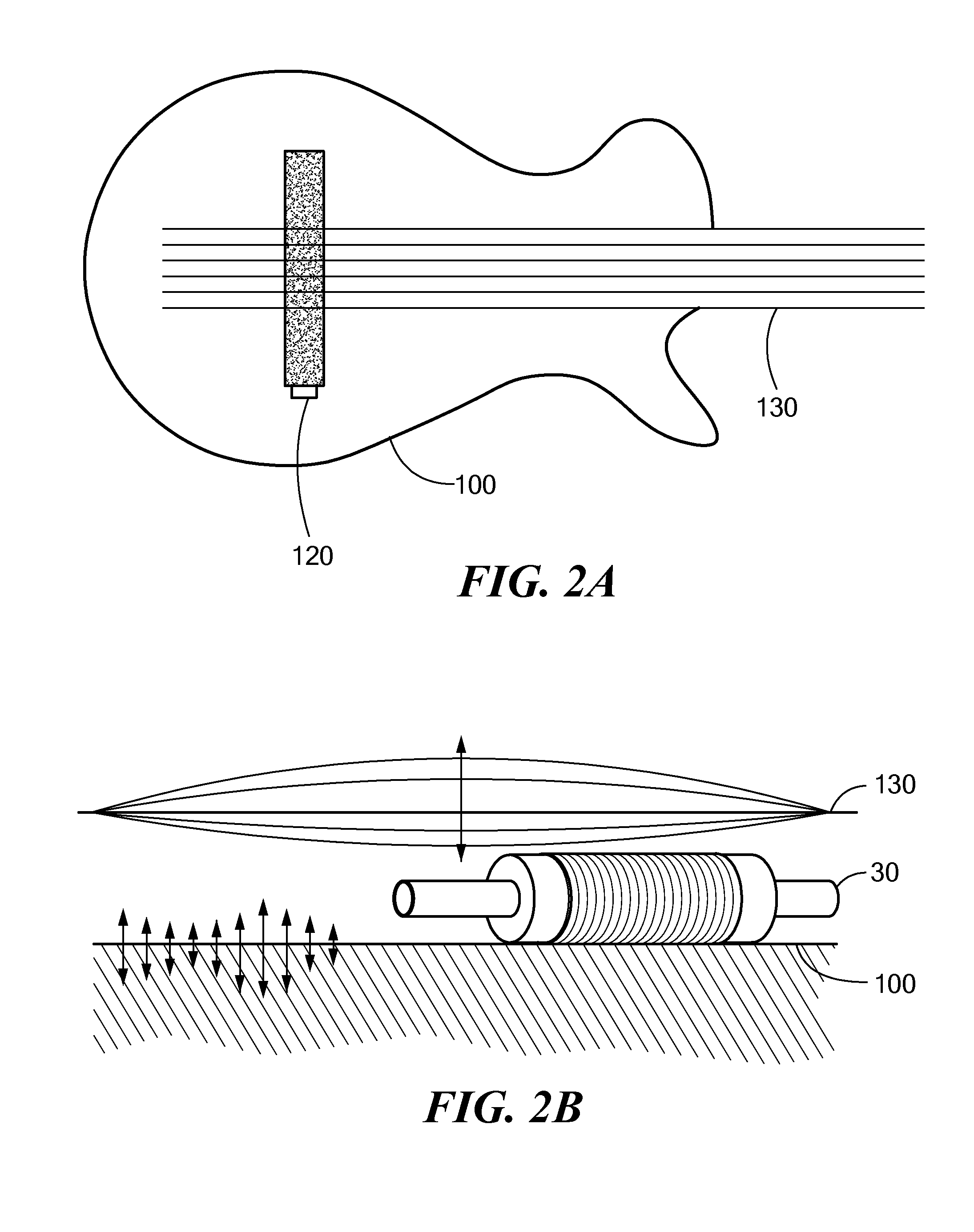
[0036]A 15 cm long, 5 cm diameter solenoid, centered inside of a triple-layer Gauss chamber, was part of the experimental set up used for detecting voltage using the magnetoelectric wires described in Example 1. A solenoid coil, instead of a Helmholtz coil, was chosen as the optimal electromagnet for generating a uniform magnetic field region over the length of the tube sensors because the radius of the coil is readily scaled down, reducing power supply requirements, while maintaining longer uniform magnetic field length. Each magnetoelectric sensor was positioned inside the center of the solenoid during measurement such that field was applied axially. Applying magnetic field along the length of the sensor causes axial strain in the wire, and, via elastic coupling, produces axial strain in the PZT tube. Voltage is detected radially across the PZT tube due to axial strain, resulting in a d31 operational mode. The Gauss chamber eff...
example 3
METGLAS-Enhanced Tube-Topology Magnetoelectric Magnetic Field Sensor
[0043]Improvement in the topology of a magnatoelectric tube sensor device is one way of increasing the sensitivity, decreasing noise floor, miniaturizeing size, eliminating magnetic bias requirement, and extending the operational bandwidth (especially at low frequency, below 100 Hz) of the device. Significant enhancement in sensitivity was realized by the addition of METGLAS ribbons to the tube-topology as described below.
[0044]The basic tube-topology, described Chen et al., 2011, consists of a magnetostrictive iron-nickel (FeNi) wire inserted and bonded, using silver epoxy, to a piezoelectric lead-zircon-titanate (PZT) tube, with a silver painted outer surface. Applying a magnetic field to this device generates strain in the FeNi wire, which transfers to the tube, and results in a separation of charge across the inner and outer surfaces of the tube. In this topology, the only magnetic strain source is along the inn...
PUM
 Abstract
Description
Claims
Application Information
 - R&D
- Intellectual Property
- Life Sciences
- Materials
- Tech Scout
- Unparalleled Data Quality
- Higher Quality Content
- 60% Fewer Hallucinations
Browse by: Latest US Patents, China's latest patents, Technical Efficacy Thesaurus, Application Domain, Technology Topic, Popular Technical Reports.
© 2025 PatSnap. All rights reserved.Legal|Privacy policy|Modern Slavery Act Transparency Statement|Sitemap|About US| Contact US: help@patsnap.com