Radiation generating apparatus and radiation imaging system

Inactive Publication Date: 2015-12-24
CANON KK
View PDF4 Cites 4 Cited by
  • Summary
  • Abstract
  • Description
  • Claims
  • Application Information

AI Technical Summary

Benefits of technology

[0007]Although the presence of the outer tube 5 prevents the increase in the damage to peripheral members caused by such discharge, it is difficult to reduce the rate of incidence of creeping microdischarge that may occur between the cathode 31 and the anode 33 to which a high voltage is applied. Hence, if such creeping microdischarge occurs repeatedly, electric discharge decomposition of the insulating liquid 4 may advance, accelerating the deterioration of the insulating liquid 4. Moreover, such creeping microdischarge may form a tracking path leading to the tubular member 32 of the radiation tube 2, accelerating the long-term deterioration of the voltage resistance of

Problems solved by technology

However, if friction occurs between an insulating solid and an insulating liquid flowing therealong, electric discharge due to the flow may occur.
Consequently, microdischarge may occur around the radiation tube 2, leading to

Method used


Image

  • Radiation generating apparatus and radiation imaging system
  • Radiation generating apparatus and radiation imaging system
  • Radiation generating apparatus and radiation imaging system

Examples


Example

Example 1

[0046]Referring to FIG. 5, a radiation tube 2 and an outer tube 5 according to Example 1 will now be described.

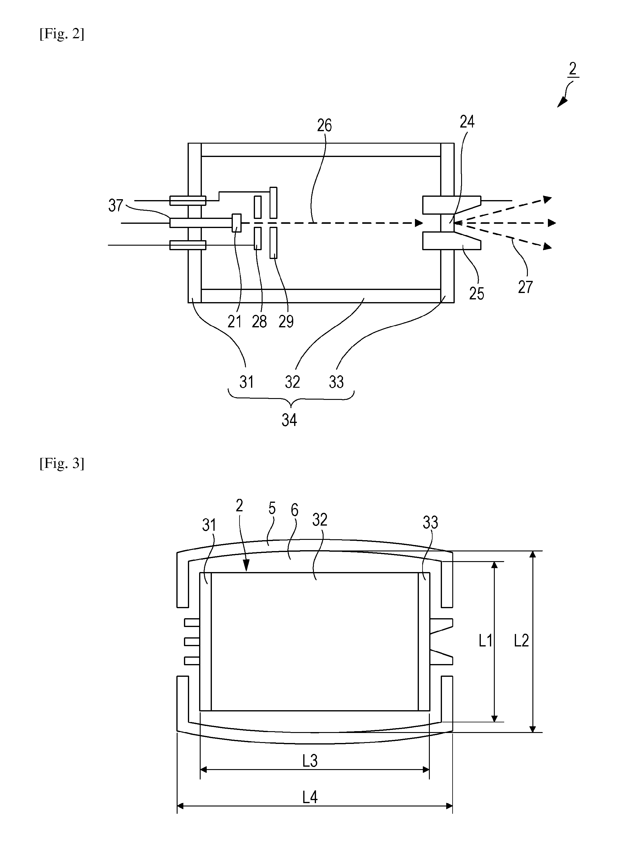
[0047]Major dimensions of the radiation tube 2 according to Example 1 were as follows: the outside diameter of the tubular member 32 was 50 mm, and a length (L3) of the radiation tube 2 inclusive of the cathode 31 and the anode 33 was 80 mm. The tubular member 32 was chiefly made of alumina ceramic. The cathode 31 was chiefly made of stainless steel. The anode 33 was chiefly made of stainless steel and copper.

[0048]Major dimensions of the outer tube 5 were as follows: a length (L4) was 100 mm, an inside diameter (L1) at each of portions thereof facing the cathode 31 and the anode 33, which were conductive members, was 60 mm, and an inside diameter (L2) at a portion thereof facing the tubular member 32 was 70 mm. The outer tube 5 was made of acrylic resin with a thickness of 5 mm.

[0049]In the above configuration, the gap 6 was provided between the outer tube 5 and t...

Example

Example 2

[0052]Another radiation generating apparatus 1 was prepared. The radiation generating apparatus 1 was the same as that of Example 1, except that the outer tube 5 illustrated in FIG. 3 was employed. Major dimensions of the radiation tube 2 were the same as those employed in Example 1. The outer tube 5 was fabricated such that the length (L4) was 100 mm, and the inside diameter was gradually increased from each of two ends thereof toward a central part thereof. Specifically, the inside diameter (L1) at the ends of the outer tube 5 facing the cathode 31 and the anode 33, respectively, was 60 mm, and the inside diameter (L2) at a portion of the outer tube 5 facing the central part of the tubular member 32 was 70 mm.

[0053]In the above configuration, the gap 6 was provided between the outer tube 5 and the radiation tube 2 such that the gaps B and C were each 5 mm and the gap at the central part of the tubular member 32 was 10 mm, whereby the cross-sectional area of the passage fo...


PUM


Abstract

A radiation generating apparatus includes a radiation tube including an electrically insulating tubular member, a cathode provided at one of two openings of the tubular member, and an anode provided at the other opening of the tubular member; an electrically insulating outer tube surrounding at least a peripheral side of the radiation tube with a separation interposed therebetween; and a container that contains the radiation tube and the outer tube. A space in the container is filled with an insulating liquid. At least a portion of a gap between the tubular member and the outer tube is wider than at least one of a gap between the cathode and the outer tube and a gap between the anode and the outer tube.

Description

TECHNICAL FIELD[0001]The present invention relates to a radiation generating apparatus that is applicable to radiation imaging in the fields of medical apparatuses and industrial apparatuses, and also relates to a radiation imaging system including the same.BACKGROUND ART[0002]In a typical radiation generating apparatus, a high voltage is applied between a cathode and an anode that are provided in a radiation tube, and electrons emitted from the cathode are applied to the anode, whereby radiation is generated. To provide a satisfactory resistance to the high voltage and to cool the radiation tube, the radiation tube included in such a radiation generating apparatus is provided in a container that is filled with an insulating liquid.[0003]Most of energy generated by the electrons applied to the anode is converted into heat. The heat generated by the anode is sequentially transmitted to the wall of the radiation tube, to the insulating liquid, and to the container, and is released int...

Claims


Application Information

Patent Timeline
IPC IPC(8): H05G1/02G01N23/04H05G1/04
CPCH05G1/025H05G1/04H01J2235/087G01N23/04H01J35/116
Inventor SUZUKI, YOSHIOYAMAZAKI, KOJI
Owner CANON KK
Why Eureka
Try Eureka