Low-temperature liquefied gas tank

a technology of liquefied gas and low temperature, which is applied in the direction of liquefaction, container discharge methods, lighting and heating apparatus, etc., can solve the problems of uneconomical, reduce loss, prevent an increase in nitrogen concentration, and limit an increase in manufacturing cost or operation cost

Inactive Publication Date: 2015-12-31
IHI CORP
View PDF4 Cites 8 Cited by
  • Summary
  • Abstract
  • Description
  • Claims
  • Application Information

AI Technical Summary

Benefits of technology

[0014]According to the low-temperature liquefied gas tank of the present disclosure, the returning unit configured to return the re-liquefaction boil off gas to the storage tank has a distributor disposed at a lower side of the liquid surface of the low-temperature liquefied gas stored in the storage tank, and configured to eject the re-liquefaction boil off gas into the low-temperature liquefied gas. For this reason, even when some of the liquid decompressed to the pressure in the storage tank is gasified when the re-liquefaction boil off gas is returned to the storage tank, since the re-liquefaction boil off gas is ejected into the low-temperature liquefied gas by the distributor, the gasified gas in the re-liquefaction boil off gas is dissolved and absorbed into the low-temperature liquefied gas. Accordingly, since the nitrogen contained in the gasified gas at a high concentration is also absorbed into the low-temperature liquefied gas, the nitrogen is prevented from being mixed with the boil off gas generated in the storage tank, delivered to the re-liquefaction facility again, and circulated therethrough. Accordingly, it is possible to prevent an increase in nitrogen concentration in the boil off gas and non-liquefaction of the boil off gas in the re-liquefaction facility, and it is possible to reduce loss due to waste of the non-liquefied gas.
[0015]In addition, since it is possible to limit an increase in nitrogen concentration in the boil off gas through a simple configuration including only a distributor, it is possible to limit an increase in manufacturing cost or operation cost.

Problems solved by technology

When the phenomenon in which the BOG is not liquefied occurs as described above, since the non-liquefied gas is separated in the gas / liquid separation drum to be delivered to a flare or the like to be discarded, it becomes uneconomical.

Method used


Image

  • Low-temperature liquefied gas tank
  • Low-temperature liquefied gas tank
  • Low-temperature liquefied gas tank

Examples


Embodiment Construction

[0021]Hereinafter, a low-temperature liquefied gas tank of the present disclosure will be described in detail with reference to the accompanying drawings. Further, in the following drawings, the scale of each member may be appropriately varied such that each member is recognizable.

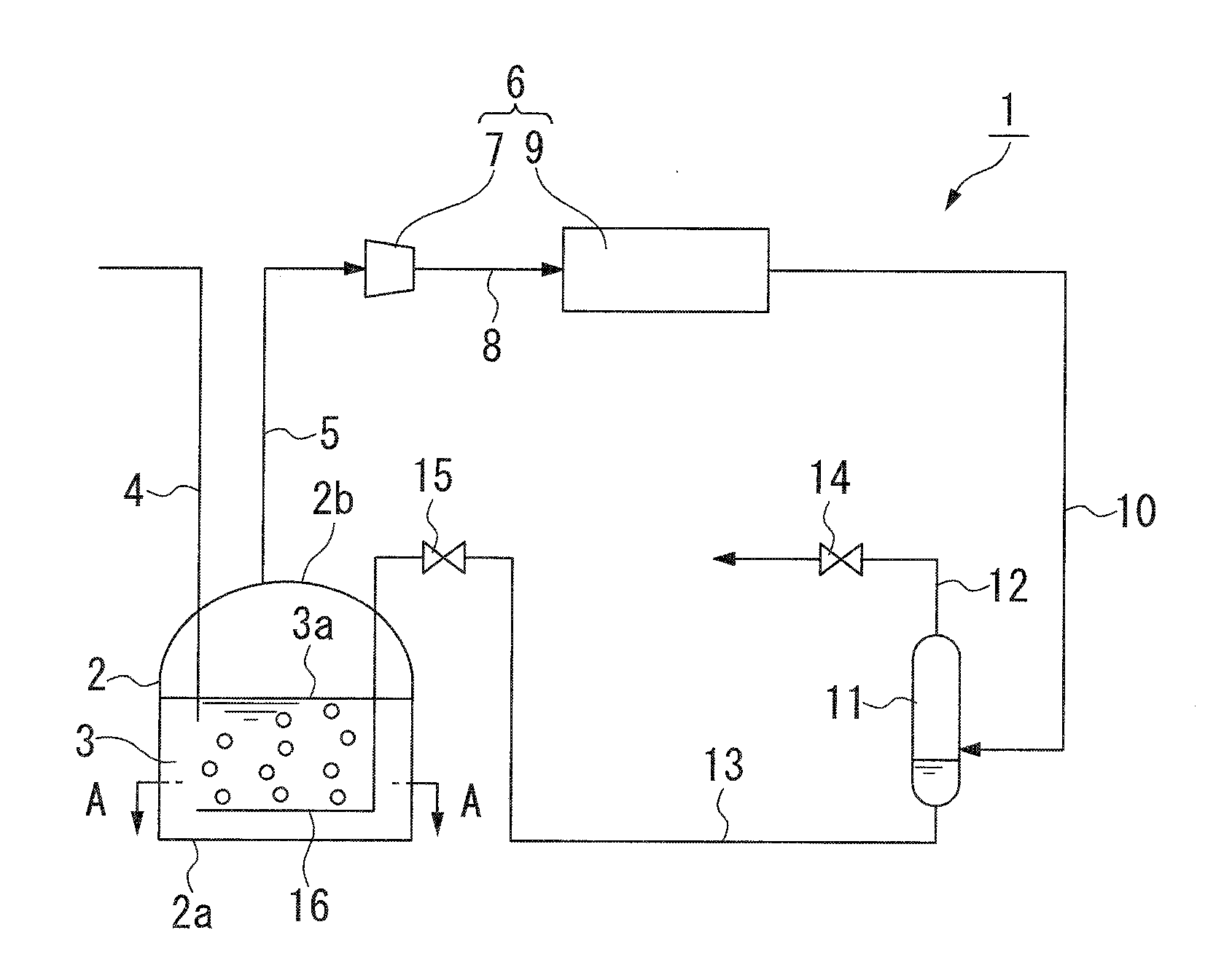
[0022]FIG. 1 is a configuration view schematically showing an embodiment of a low-temperature liquefied gas tank of the present disclosure. FIG. 1 shows a low-temperature liquefied gas tank 1, and a storage tank 2. The storage tank 2 is configured to store a low-temperature liquefied gas such as liquefied natural gas (LNG) or liquefied petroleum gas (LPG), and further, methane, ethane, propane, or the like. In the embodiment, the storage tank 2 is a tank configured to store the liquefied natural gas (LNG) 3.

[0023]The storage tank 2 is configured to include an inner tank formed of, for example, a metal, and an outer tank formed of concrete. The inner tank is a container configured to directly store a liquef...


PUM


Abstract

A low-temperature liquefied gas tank is a low-temperature liquefied gas tank including a storage tank configured to store a low-temperature liquefied gas, and a re-liquefaction facility configured to liquefy boil off gas generated in the storage tank. A returning unit configured to return a re-liquefaction boil off gas liquefied in the re-liquefaction facility to the storage tank is provided. The returning unit has a distributor disposed under a liquid surface of the low-temperature liquefied gas stored in the storage tank and configured to eject the re-liquefaction boil off gas into the low-temperature liquefied gas.

Description

TECHNICAL FIELD[0001]The present disclosure relates to a low-temperature liquefied gas tank.[0002]This application is a continuation application based on a PCT Patent Application No. PCT / JP2014 / 061590, filed Apr. 24, 2014, whose priority is claimed on Japanese Patent Application No. 2013-103287, filed May 15, 2013. The contents of both the PCT application and the Japanese Patent Application are incorporated herein by reference.BACKGROUND ART[0003]In the related art, in a low-temperature liquefaction tank including a storage tank configured to store a low-temperature liquefied gas such as liquefied natural gas (LNG) or the like, a boil off gas (hereinafter referred to as BOG) generated by gasifying a low-temperature liquefied gas is re-liquefied to return to a liquefied gas as a form of a product. That is, the generated BOG is compressed and cooled in a re-liquefaction facility to be re-liquefied, a gas that is not liquefied using a gas / liquid separation drum is separated, and then t...

Claims


Application Information

Patent Timeline
Patent Type & Authority Applications(United States)
IPC IPC(8): F25J1/00F17C9/02
CPCF17C13/00F17C2203/0604F17C2203/0678F17C2221/033F17C2221/035F17C2223/0153F17C2223/0161F17C2265/034F17C9/02F25J1/0025
Inventor SAKAI, YUKITOMO
Owner IHI CORP
Why Eureka
Try Eureka