Optical sensor head and optical sensor system

a sensor head and optical sensor technology, applied in the direction of phase-affecting property measurement, analysis by material excitation, instruments, etc., can solve the problems of high cost, increased size of the apparatus, difficult high-precision detection on the molecular level, etc., to achieve favorable sensitivity, reduce size, and increase sensitivity

Inactive Publication Date: 2015-12-31
SHARP KK
View PDF4 Cites 0 Cited by
  • Summary
  • Abstract
  • Description
  • Claims
  • Application Information

AI Technical Summary

Benefits of technology

[0022]According to optical sensor system according to the first aspect, the sensitivity may be increased and the size may be reduced compared to an optical sensor system of the related art. Here, the optical sensor system of the related art signifies a “system that detects a variation amount of an environmental parameter from reflected light or transmitted light when a reactant is irradiated with light” and the details thereof will be described later.
[0023]According to the optical sensor head according to the second aspect, because the intensity distribution of light in the through hole becomes weak in the vicinity of the emission surface of light and becomes strong in the vicinity of the opposing surface of light, detection may not easily influenced influence from the outside of the through hole and may be performed with a favorable sensitivity of only variations in the refractive index inside the through hole. Therefore, detection may be performed on the molecular level if the opening size in the opposing surface of the through hole is made sufficiently small. In order to detect only the detection target able to enter the opening in the opposing surface of the through hole, detection may be performed after sorting the detection target with the opening size. Since the detection target may only be present inside the through hole, the sample volume may be reduced. The size may be reduced because a separate light source is made unnecessary.

Problems solved by technology

However, because a complex configuration formed from a light source, lens, prism and the like is necessary in executing this method, precision during assembly, strict temperature management so that variations over time do not occur, correction of shifts that arise and the like are necessary, costs are incurred, and the size of the apparatus increases.
High precision detection on the molecular level is difficult.

Method used


Image

  • Optical sensor head and optical sensor system
  • Optical sensor head and optical sensor system
  • Optical sensor head and optical sensor system

Examples


embodiment 1

[0038]The optical sensor system according to Embodiment 1 of the invention and the examples thereof will be described with reference to FIGS. 1 to 4.

[Configuration of Optical Sensor System]

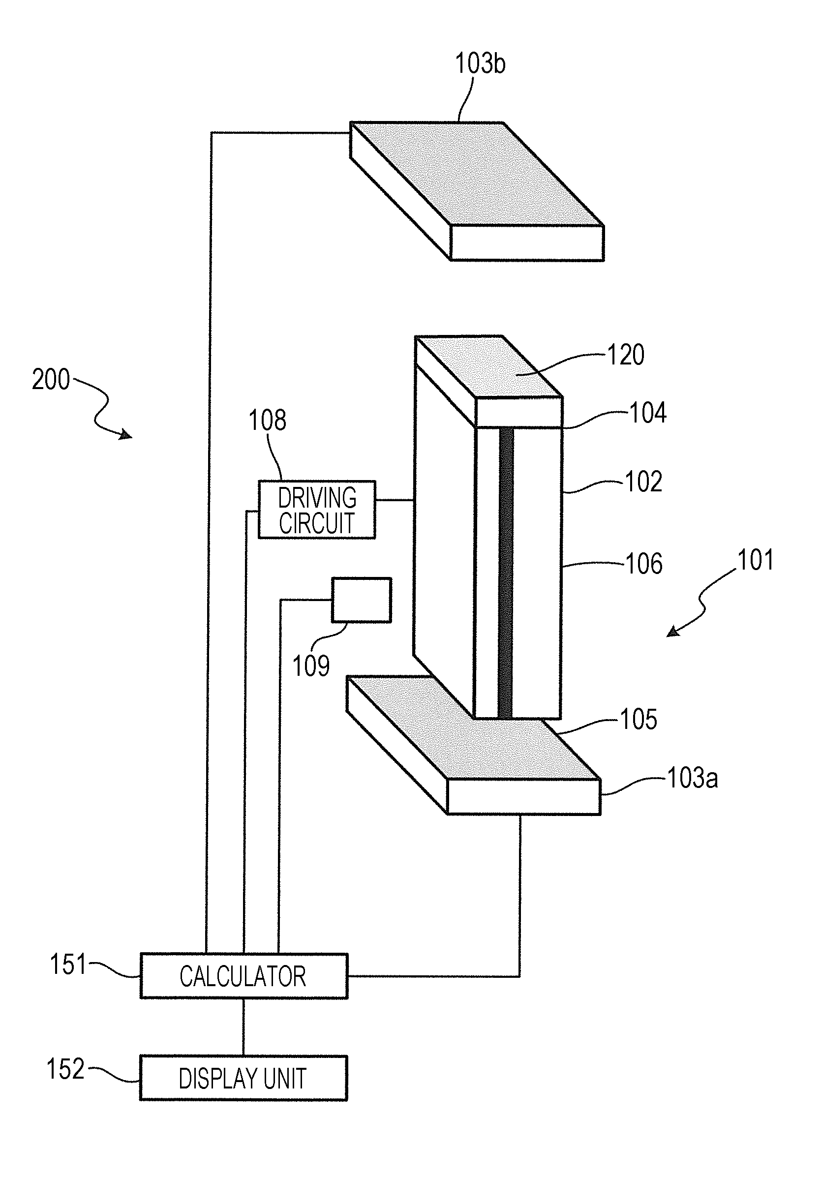
[0039]The optical sensor system 200 according to the embodiment, as shown in FIG. 1, is configured from a light emitting device 102, a reactant 120, two detectors 103a and 103b, a driving circuit 108, a calculator 151, and a display unit 152. The light emitting device 102, reactant 120, and detectors 103a and 103b configure the optical sensor head 101. Although not shown in the drawings, the optical sensor head 101 is integrated by being packaged. The light emitting device 102 includes a first reflection surface 104, a second reflection surface 105 opposing the first reflection surface 104, and a waveguide 106 provided between the first reflection surface 104 and the second reflection surface 105. The reactant 120 is formed on the first reflection surface 104. The two detectors 103a and 103b are a...

example 1

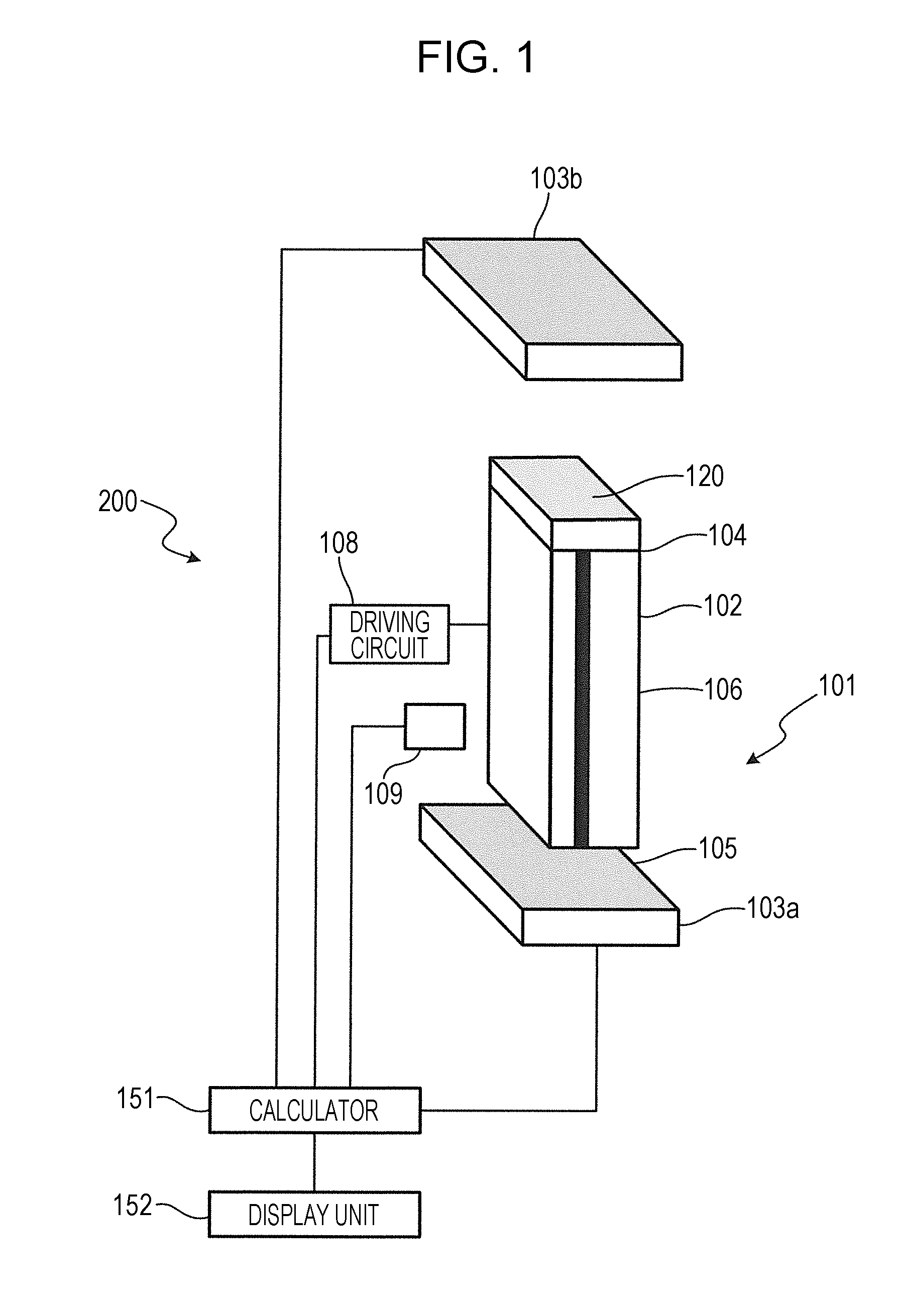
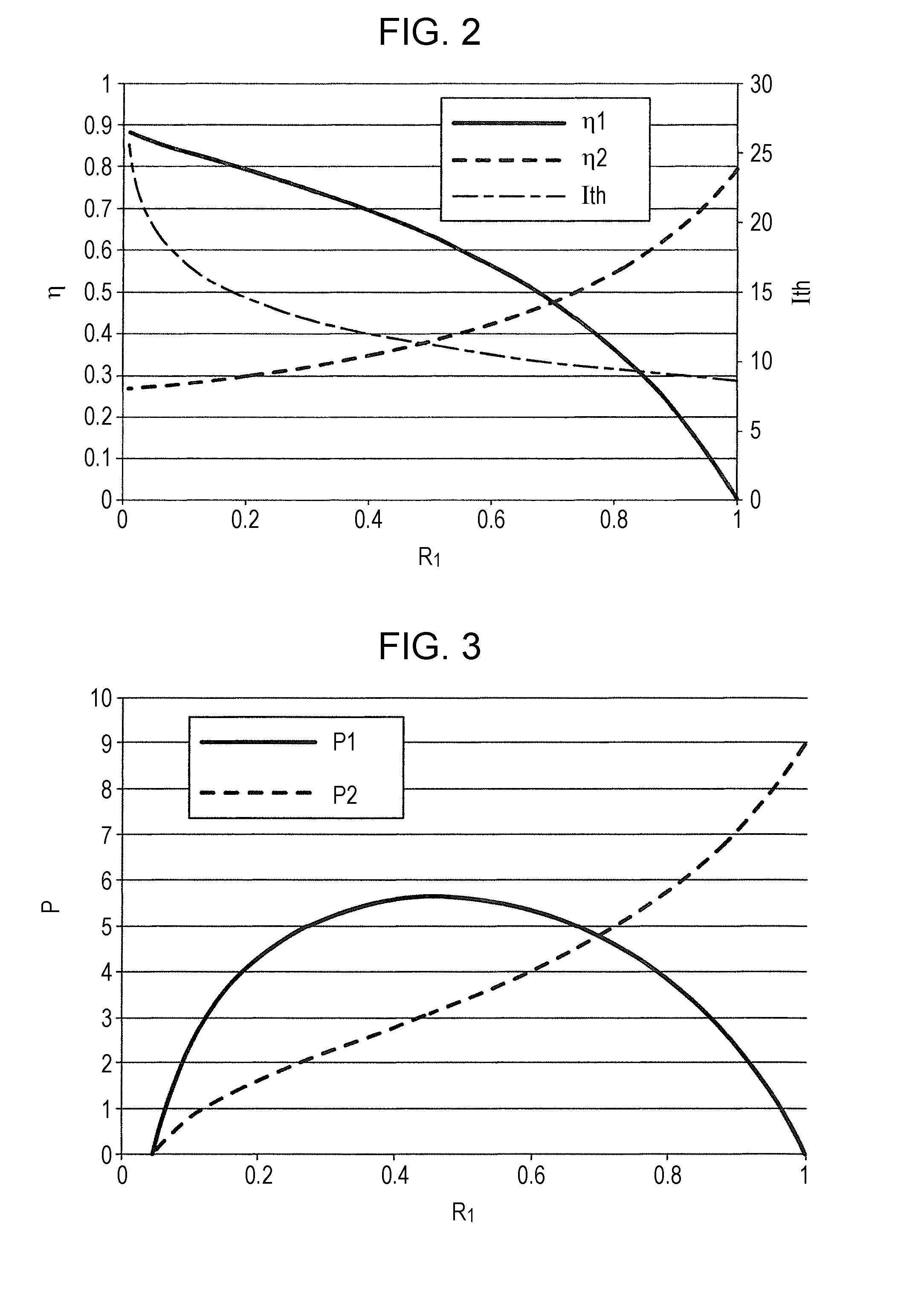
[0082]For Example 1, the reflectivity R1 of the first reflection surface 104 before the reactant 120 is reacted (initial state) is 0.3 in the specific example described in FIGS. 2 to 4.

[0083]With reference to FIG. 4, in R1=0.3, it is found that the above (5) establishes either of the light intensity P1 of light radiated from the first reflection surface 104 and the light intensity P2 of light radiated from the second reflection surface 105. That is, in the case of Example 1, even if either of the light intensity P1 or the light intensity P2 is detected, it is found that the sensitivity is higher than the optical sensor system of the related art described above.

[0084]In the embodiment, the reflectivity R2 of the second reflection surface 105 becomes higher than the reflectivity R1 of the first reflection surface 104 by becoming 0.7, the light in the light emitting device 102 is not easily transmitted to the outside, and the differential efficiency η1 becomes higher than the different...

example 2

[0087]For Example 2, the reflectivity R1 of the first reflection surface 104 before the reactant 120 is reacted (initial state) is 0.7 in the specific example described in FIGS. 2 to 4.

[0088]With reference to FIG. 4, in Example 2, it is found that the above (5) establishes either of the light intensity P1 of light radiated from the first reflection surface 104 and the light intensity P2 of light radiated from the second reflection surface 105. That is, in the case of Example 2, even if either of the light intensity P1 or the light intensity P2 is detected, it is found that the sensitivity is higher than the optical sensor system of the related art described above.

[0089]With reference to FIG. 3, in a range were the reflectivity R1 is 0.45 to 0.7, it is found that the light intensity P1 of light radiated from the first reflection surface 104 is reduced slightly as the reflectivity R1 of the first reflection surface 104 increases. Accordingly, if the reflectivity R1 of the first reflec...


PUM

PropertyMeasurementUnit
aspect ratioaaaaaaaaaa
light intensityaaaaaaaaaa
reflectivity R1aaaaaaaaaa

Abstract

An optical sensor head detects only the refractive index inside a through hole and is not susceptible to influence from the outside of the through hole. An optical sensor head includes a light emitting device 2 in which a first reflection surface 4, a second reflection surface 5 that opposes the first reflection surface 4 and a waveguide 6 provided between the first reflection surface 4 and the second reflection surface 5 are formed; a light blocking film 7 in which a through hole 8 for generating near-field light is provided, and that is formed on the first reflection surface 4; and a detector 3 that detects the light intensity of light emitted from the light emitting device 2 through the second reflecting surface 5. The opening area of the through hole 8 on the emission surface 7b of the light of the light blocking film 7 is larger than the opening area of the through hole 8 on the opposing surface 7a of the light blocking film 7 opposing the first reflection surface 4.

Description

TECHNICAL FIELD[0001]The present invention relates to an optical sensor head and an optical sensor system.BACKGROUND ART[0002]In general, a method of detecting variations in the resonance state of an optical resonator in various optical sensors is used in various fields in light having high sensitivity and a marker being unnecessary. For example, in PTL 1, the returning light from an optical recording medium returns to the semiconductor laser, the oscillation state of the semiconductor laser is varied, and the variations are detected by a monitor photodetector (PD).[0003]In PTL 2, the oscillator is formed integrally with the semiconductor laser and the monitor PD as an oscillation detector, and contributes intensity modulation to the oscillation state of the semiconductor laser through the returning light from the oscillator, and variations in the eigen frequency of the oscillator and the pressure, temperature, displacement, flow rate and the like that are sources thereof are measur...

Claims


Application Information

Patent Timeline
Patent Type & Authority Applications(United States)
IPC IPC(8): G01N21/65G01N21/41
CPCG01N21/553G01N21/7746G01N2021/7776G01N21/41G01N21/658G01N2201/06113G01N2201/068G01N2201/08
Inventor KITAZAWA, TAZUKOIWATA, NOBORUSATO, TAKANOBU
Owner SHARP KK
Why Eureka
Try Eureka