Intelligent switch capacitor

a capacitor and intelligent technology, applied in the direction of electrical energy, liquid/fluent solid measurement, instruments, etc., can solve the problems of switch and capacitor not being able power capacitor burnout, etc., to achieve rapid capacitor switching of power capacitors, reduce fault rate, and protect the effect of speed

Active Publication Date: 2015-12-31
GYRK INT TECH
View PDF4 Cites 13 Cited by
  • Summary
  • Abstract
  • Description
  • Claims
  • Application Information

AI Technical Summary

Benefits of technology

[0019]The beneficial effects of the present invention are that: 1. the capacitor switch and the power capacitor are matched and designed in an optimal way, and the switch and the power capacitor are integrated, so that the fault rate can be greatly reduced and meanwhile rapid capacitor switching of the power capacitor can be achieved; 2. the capacitor has an electronic thermal protection function, and such overheating protection function, based on a thermistor installed on the capacitor core, has characteristics of precise protection temperature and high protection speed with the protection temperature being adjustable, in which the function of delayed protection and non-destructive protection cannot be achieved by conventional mechanical protection devices; 3. the harmonic current can be detected accurately and rapidly by means of the harmonic current detection and protection function, so that the hidden trouble of capacitor damage and power grid accidents caused by resonance of a power factor correction (PFC) power capacitor in a power grid system are completely eliminated; and 4. a discharge resistor connected in parallel to the capacitor is removed, so that the loss of the power capacitor is minimized while safe use of the capacitor is ensured.

Problems solved by technology

In practice, the series-connected reactor can only solve part of the problem of high-order harmonic resonance, and cannot solve the resonance problem fundamentally, and even with the reactor, burnout of the power capacitor also occurs due to high-order resonance.
When the capacitor is disconnected through the switch, the residual voltage of one phase of capacitor always reaches 1.36 times the peak supply voltage, and the capacitor must be discharged before being connected again, so that such combination of the switch and the capacitor cannot achieve rapid capacitor switching.
In addition, a discharge resistor must be installed inside the conventional power capacitor as required by safety specifications, but the discharge resistor produces large power consumption.
However, the explosion-proof mechanism is unrecoverable, and the capacitor can no longer be used once the explosion-proof mechanism operates.
Besides, such mechanical explosion-proof mechanism has high requirements on sealing of the capacitor, and the thermal expansion explosion-proof mechanism does not operate upon leakage.
Further, such explosion-proof mechanism has low response speed, and cannot respond quickly to protect the capacitor when resonance occurs in the capacitor circuit.
However, such intelligent capacitor still cannot effectively solve the problems of protection against capacitor heating, harmonic protection, power consumption of the capacitor switch, and rapid capacitor switching.
However, the external protection device is rarely used because of the cost and mainly because the external protection device cannot detect the actual operating status in a capacitor core.
The external protection device makes little sense as it cannot achieve accurate and rapid protection.
Due to the cost of a small-capacity power capacitor and the cost of a capacitor switch, conventional reactive compensation devices using power capacitors and having power lower than 30 kvar generally cannot achieve graded compensation, while reactive compensation devices with high power cannot achieve fine compensation.
In view of the above, the power capacitor operates in a poor power grid environment due to the presence of a large amount of harmonics.
Because there is no effective, reliable and low-cost way of protecting the power capacitor, the protection of the low-voltage power capacitor remains to be a tough problem.

Method used


Image

  • Intelligent switch capacitor
  • Intelligent switch capacitor
  • Intelligent switch capacitor

Examples


Embodiment Construction

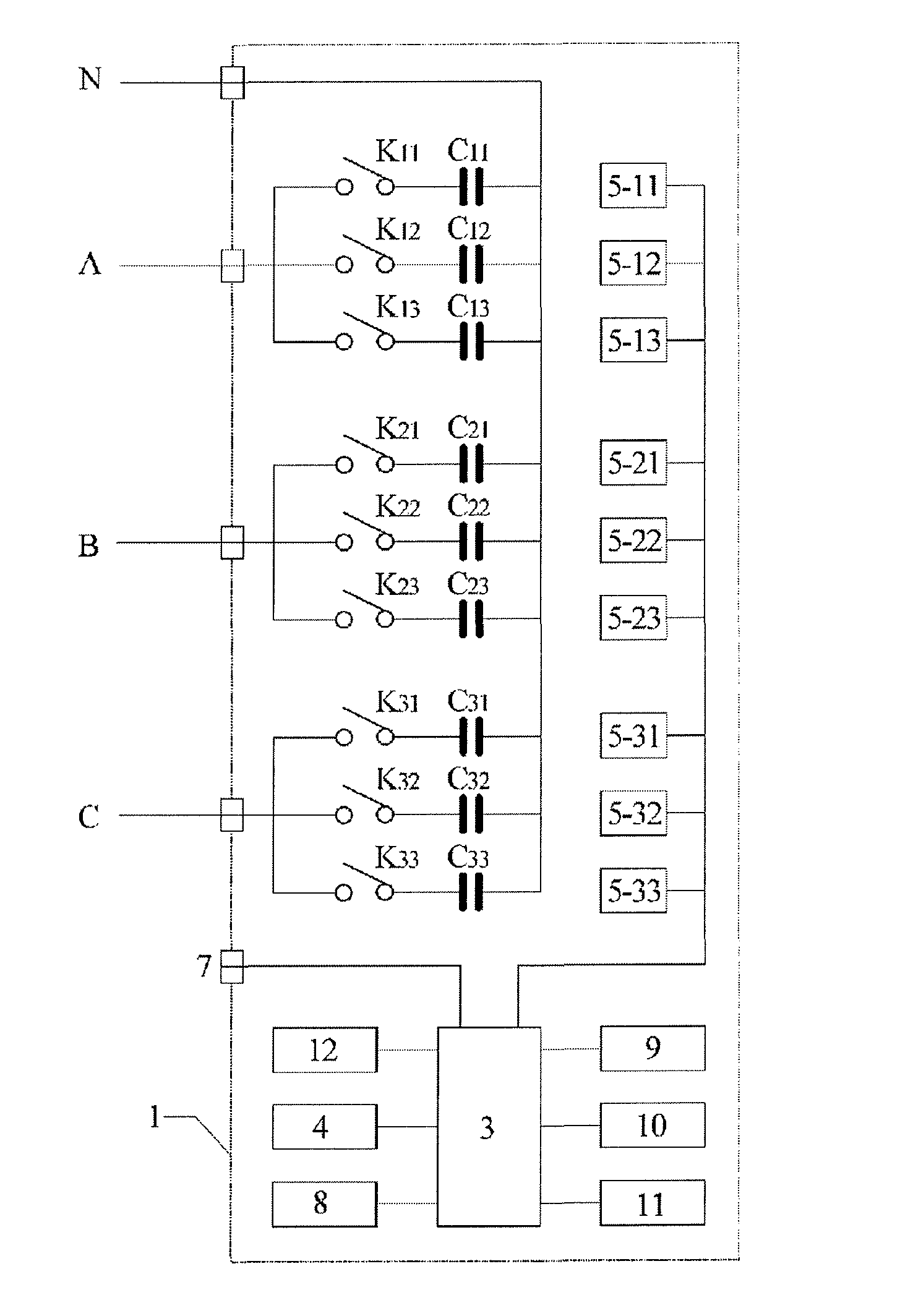
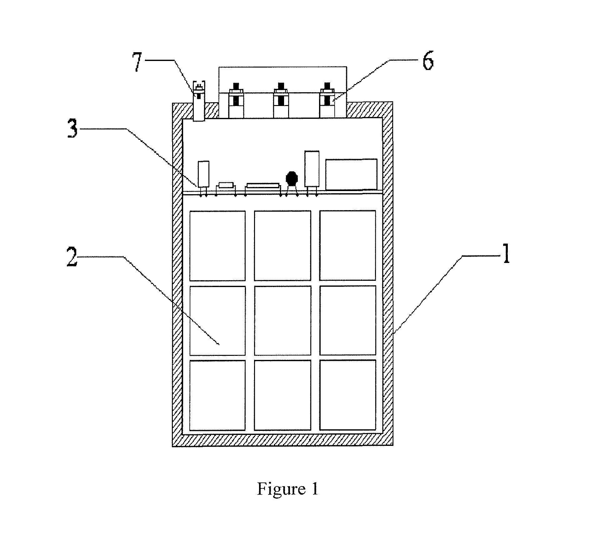
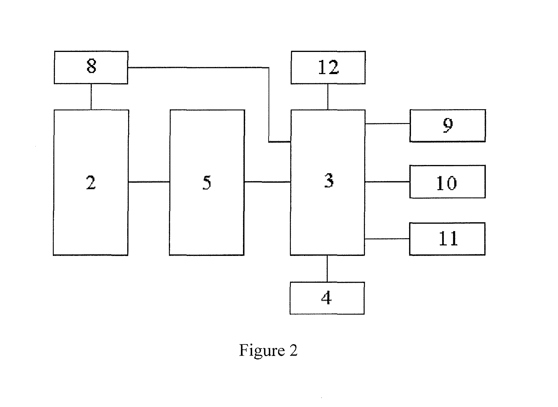
[0031]As shown in FIG. 1 and FIG. 2, an intelligent switch capacitor according to an embodiment of the present invention includes a housing 1. A capacitor core 2 is disposed inside the housing 1. An intelligent switch circuit board 3 is placed on a top end of the capacitor core 2. The intelligent switch circuit board 3 is connected to a single-chip microcomputer 4, a capacitor switch 5, a temperature measurement module 9, a current measurement module 10, and a current harmonic component measurement module 11. The capacitor switch 5 is composed of three switches in internal triangle connection with the capacitor core 2. A leading-out terminal 6 of a three-phase power line and a control interface 7 for controlling the switch are disposed in the middle of a top end of the housing 1. A bottom of the control interface 7 is connected to the intelligent switch circuit board 3. A wire fastening device is disposed inside the leading-out terminal of the three-phase power line. The wire fasten...


PUM


Abstract

The present invention relates to an intelligent switch capacitor, which comprises a shell. The shell is provided with a capacitor core internally. A temperature sensor is arranged on the capacitor core. A top end of the capacitor core is connected to an intelligent switch wiring board. The intelligent switch wiring board is connected to a single chip computer, a capacity-switch, a temperature measurement module, a current measurement module and a current harmonic component measurement module, wherein the capacitor switch is connected to the capacitor core in an inner triangle way. Beneficial effects of the present invention are: 1. A switch and a power capacitor are integrated into a whole, which can implement quick capacity-switching and cutting of the switch; 2. The capacitor has an electronic thermal protection function; 3. Possibilities of capacitor damages and power grid accidents caused by resonance of a PFC capacitor in a power grid system are eliminated completely; 4. A power capacitor loss is reduced.

Description

TECHNICAL FIELD[0001]The present invention relates to an assembly of a capacitor switch and a low-voltage alternating current capacitor, and more particularly to a power capacitor used for low-voltage power grid compensation or filtering and provided with an intelligent switch therein.BACKGROUND[0002]A power capacitor is a circuit element that must be used in power system compensation and filtering. During compensation or filtering of a power grid, the power capacitor is connected or disconnected through a capacitor switch, or the capacitor switch and the power capacitor are always used in combination. However, the conventional power capacitor and capacitor switch are produced in two different industries, and the power sector needs to separately purchase the two products and assemble them on equipment prior to use. Because power capacitors of different sizes require different switches, matching of different power capacitors with suitable capacitor switches must be considered in use....

Claims


Application Information

Patent Timeline
Patent Type & Authority Applications(United States)
IPC IPC(8): G06F1/32H02J3/18
CPCH01G4/40H01G2/18H02J3/18Y02P80/112H01G4/38Y02E40/30G06F1/32Y02P80/10
Inventor WANG, HAI
Owner GYRK INT TECH
Why Eureka
Try Eureka