Bidirectional dc/dc converter

a dc/dc converter and bi-directional technology, applied in the direction of electric variable regulation, process and machine control, instruments, etc., can solve the problems of complex circuit configuration, inability to control output voltage to or below a certain value, and increase in siz

Active Publication Date: 2015-12-31
FUJI ELECTRIC CO LTD
View PDF3 Cites 29 Cited by
  • Summary
  • Abstract
  • Description
  • Claims
  • Application Information

AI Technical Summary

Benefits of technology

[0022]According to embodiments of the invention, by frequency modulation control at a frequency equal to or lower than the resonance frequency of the series resonance circuit being adopted as the control method when power is supplied from the first direct current voltage supply to the second direct current voltage supply, and fixed frequency control being adopted as the control method when power is supplied from the second direct current voltage supply to the first direct current voltage supply, a circuit that regulates the constants of the series resonant circuit becomes unnecessary, and a small-sized bidirectional DC / DC converter with a wide input / output voltage range can be realized. Also, by switching frequency modulation control in the vicinity of the resonance frequency of the series resonant circuit to fixed frequency control when power is supplied from the first direct current voltage supply to the second direct current voltage supply , the minimum operating frequency of the bridge circuit can be set high, and the bidirectional DC / DC converter can be further reduced in size owing to a reduction in size of the isolating transformer.

Problems solved by technology

Therefore, the existing bidirectional DC / DC converter is such that the circuit configuration is complex, and there is a problem in that the size increases.
However, as previously mentioned, the output voltage cannot be controlled to or below a certain value when carrying out PFM control of a resonant inverter, even when the switching frequency is increased, because there is concern that the desired voltage V1 cannot be output when there is a light load or no load.
That is, it is understood that it is difficult to have an application with a wide input / output voltage range when carrying out PFM control of a resonant bidirectional DC / DC converter.

Method used


Image

  • Bidirectional dc/dc converter
  • Bidirectional dc/dc converter
  • Bidirectional dc/dc converter

Examples


first embodiment

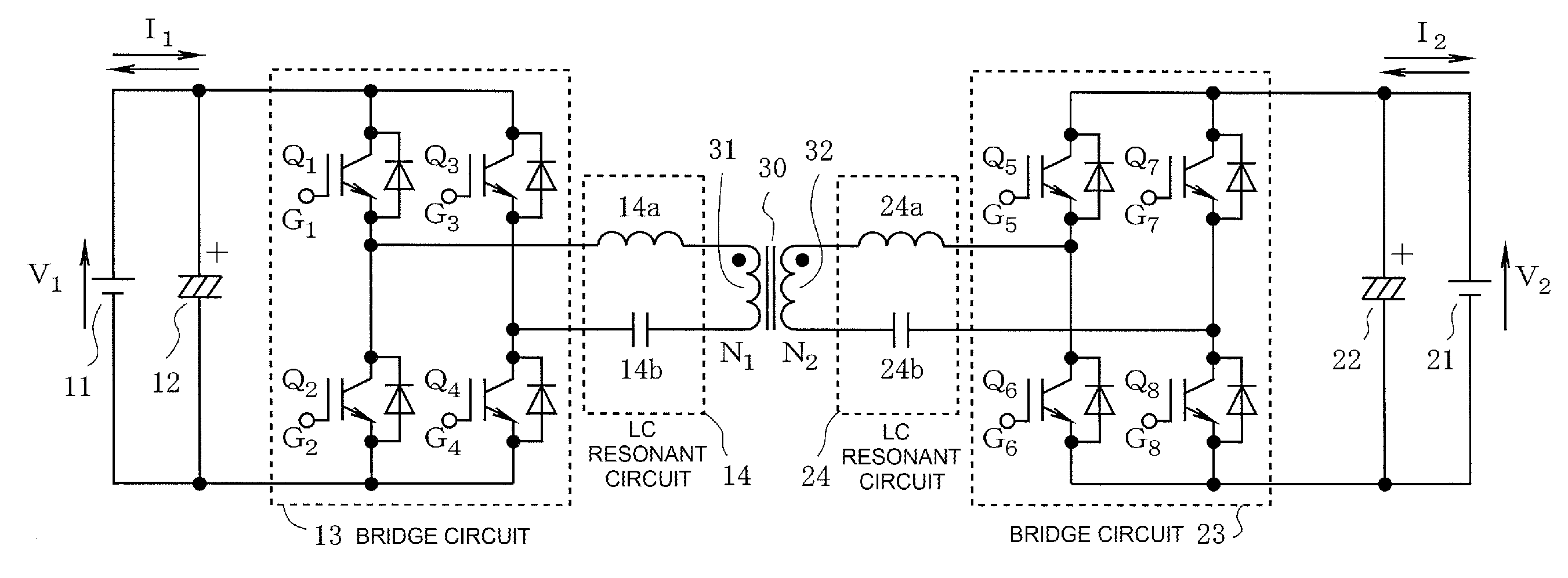
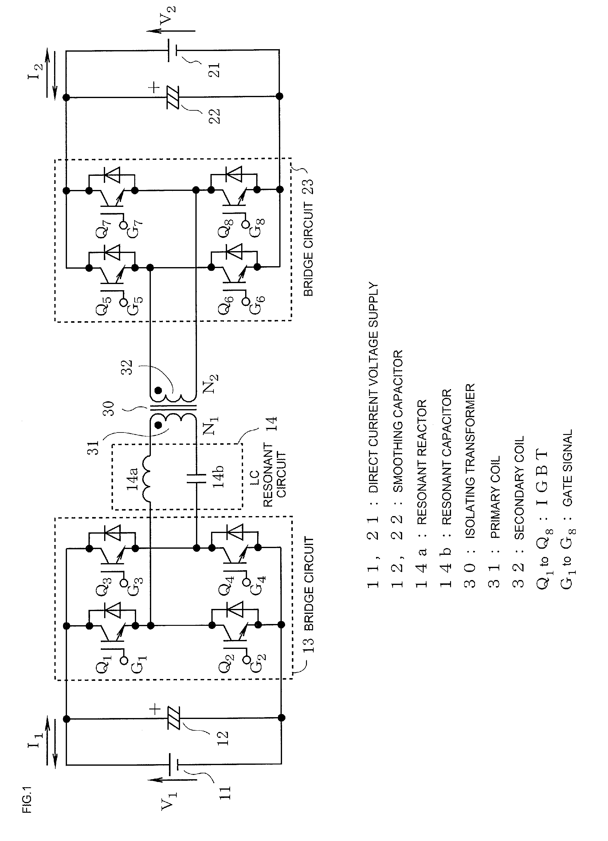
[0042]Because operations when power flows from the direct current voltage supply 21 to the direct current voltage supply 11 are the same as in the first example, a description will be omitted. As heretofore described, according to the second example, the voltage of the direct current voltage supply 11 can be V1, and the voltage of the direct current voltage supply 21 can be controlled within the range of V2min to V2max, whether power flows from the direct current voltage supply 11 to the direct current voltage supply 21 or from the direct current voltage supply 21 to the direct current voltage supply 11, and the size can be reduced further than in the first example. In the first embodiment, the LC resonant circuit 14 acting as a series resonant circuit is configured by the resonant reactor 14a and resonant capacitor 14b being connected in series, but the LC resonant circuit may be configured utilizing the leakage inductance of the isolating transformer 30 instead of the resonant rea...

second embodiment

[0043]Also, in the embodiment of FIG. 1, a description has been given of a case wherein IGBTs are used as the semiconductor switch elements Q5 through Q8 configuring the bridge circuits 13 and 23, but the same advantages can also be obtained when using MOSFETs as semiconductor switch elements Q11 through Q18 (gate signals are shown as G11 through G18), as shown in FIG. 4. In this case, a bridge circuit acting as a rectifier circuit (a bridge circuit 25 when power flows from the direct current voltage supply 11 to the direct current voltage supply 21, a bridge circuit 15 when power flows from the direct current voltage supply 21 to the direct current voltage supply 11), may be caused to carry out a synchronous rectification operation.

REFERENCE SIGNS AND NUMERALS ARE AS FOLLOWS:


PUM


Abstract

A bidirectional DC/DC converter includes first and second control circuits, and first and second bridge circuits respectively connected to first and second direct current voltage supplies. In one embodiment variant, when power is supplied from the first direct current voltage supply to the second direct current voltage supply, the first control circuit carries out PFM control of the first bridge circuit at a frequency equal to or lower than the resonance frequency of an LC resonant circuit in accordance with a control amount based on the voltage and current of the second direct current voltage supply. When power is supplied in the other direction, the second control circuit carries out fixed frequency control of the second bridge circuit, using phase shift control or the like, in accordance with a control amount based on the voltage and current of the first direct current voltage supply.

Description

CROSS-REFERENCE TO RELATED APPLICATIONS[0001]This application is a continuation application, filed under 35 U.S.C. § 111(a), of International Application PCT / JP2014 / 063013, filed on May 16, 2014, and claims benefit of foreign priority to Japanese Patent Application 2013-145469, filed Jul. 11, 2013, the disclosure of each of which is incorporated herein by reference.BACKGROUND[0002]1. Field[0003]The present disclosure relates to a bidirectional DC / DC converter that carries out DC / DC conversion in two directions via an isolating transformer, and in particular, relates to a bidirectional DC / DC converter suited to an application wherein the input / output voltage range is wide, for example, as a battery charger.[0004]2. Description of Related Art[0005]A so-called resonant bidirectional DC / DC converter that utilizes the resonance phenomenon of an LC resonant circuit configured of a reactor and capacitor is disclosed in patent application publication JP-A-2012-70491 (e.g., paragraphs [0019]...

Claims


Application Information

Patent Timeline
Patent Type & Authority Applications(United States)
IPC IPC(8): H02M3/335
CPCH02M3/33584H02M2007/4815Y02B70/1441Y02B70/1433H02M3/33546Y02B70/10H02M7/4815
Inventor MATSUBARA, KUNIONISHIKAWA, YUKIHIRO
Owner FUJI ELECTRIC CO LTD
Why Eureka
Try Eureka