Methods and devices for implantation of intraocular pressure sensors

a technology of intraocular pressure and sensors, which is applied in the field of devices and methods for implanting intraocular pressure sensors, can solve the problems of degrading visual function and damage to delicate structures, and achieve the effect of improving charging and telemetry

Active Publication Date: 2016-01-07
INJECTSENSE INC
View PDF17 Cites 12 Cited by
  • Summary
  • Abstract
  • Description
  • Claims
  • Application Information

AI Technical Summary

Benefits of technology

[0018]In still other embodiments, the sensor device may include at least a first and second anchoring member such that anchoring includes deploying the first anchoring member along the sclera outside of the vitreous body and deploying the second anchoring member along the sclera inside the vitreous body so as to inhibit axial movement of the IOP sensor along the insertion axis in both proximal and distal directions after implantation. Each of the first and second anchoring members may include one or more anchoring members. In another aspect, anchoring against

Problems solved by technology

Because the anterior chamber is a particularly sensitive region, great care must be taken to avoid contacting the various

Method used


Image

  • Methods and devices for implantation of intraocular pressure sensors
  • Methods and devices for implantation of intraocular pressure sensors
  • Methods and devices for implantation of intraocular pressure sensors

Examples


Embodiment Construction

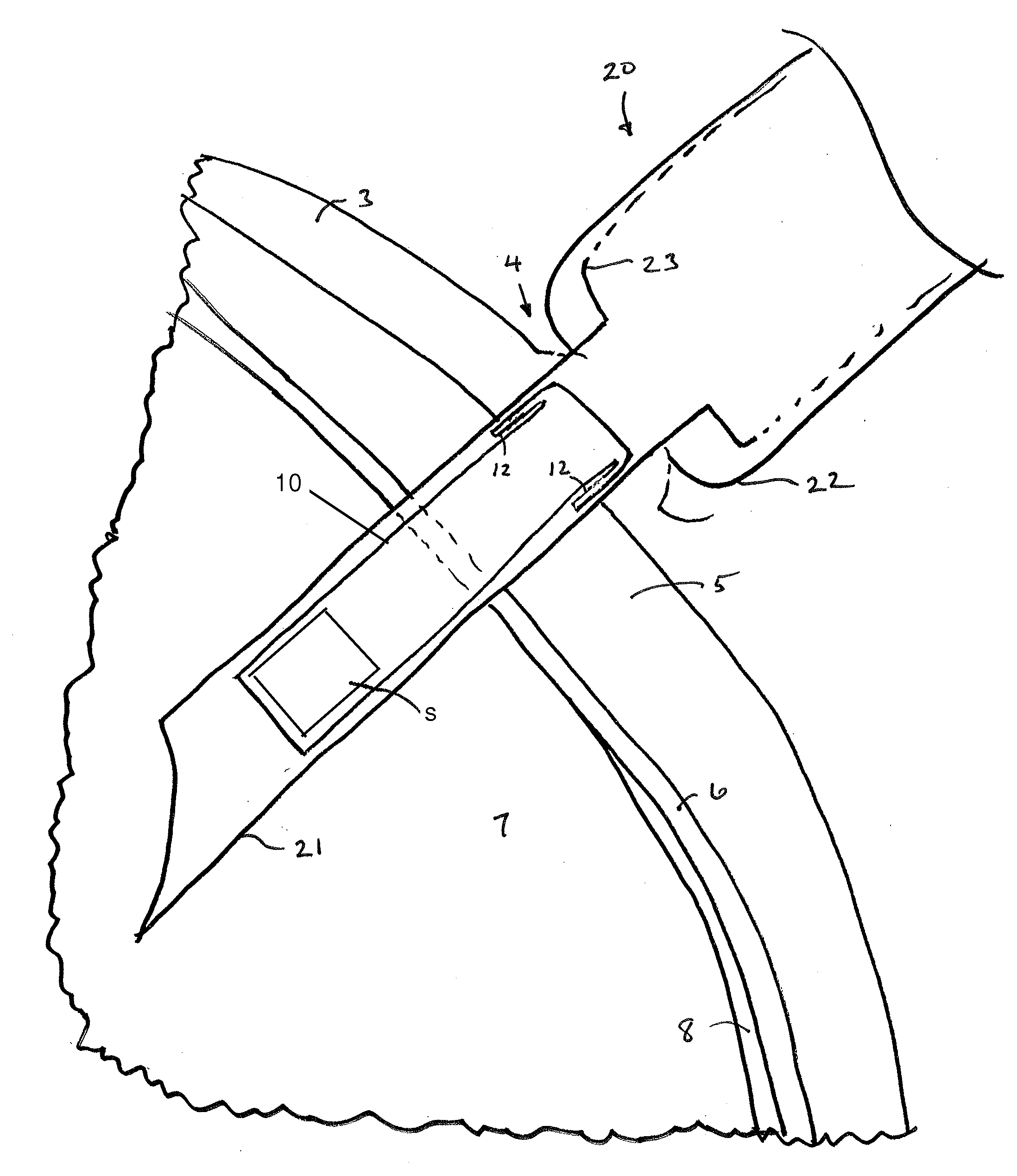
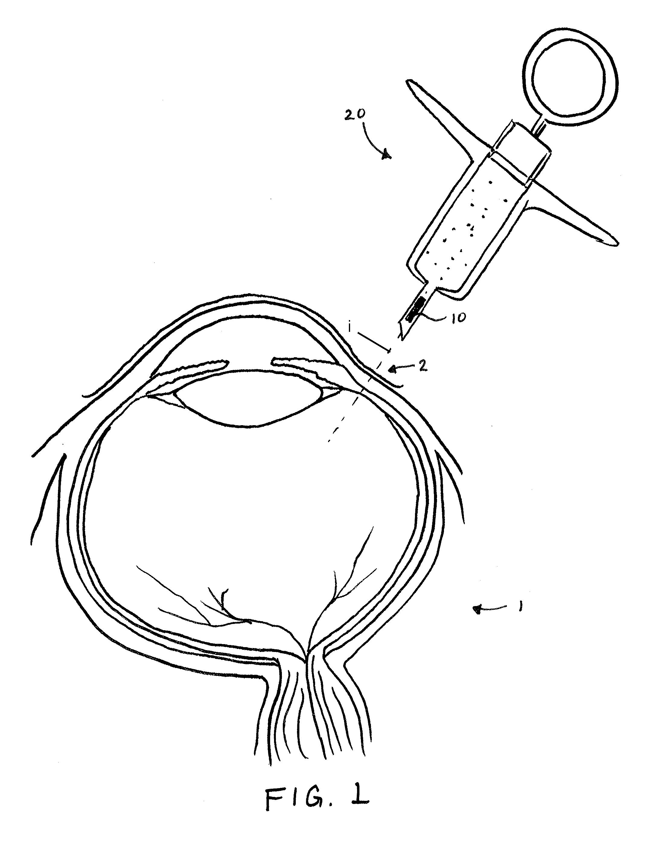
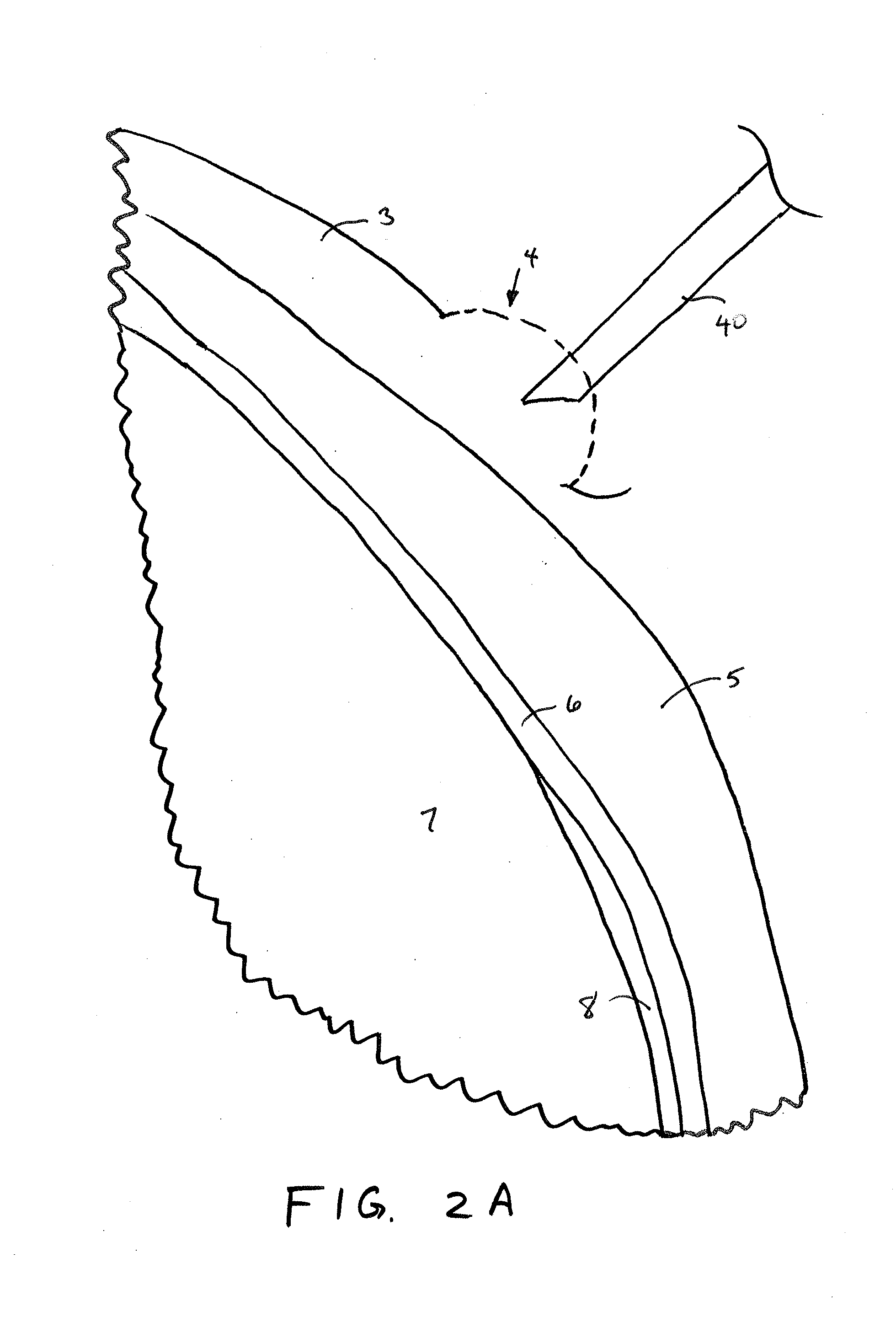
[0032]FIG. 1 is an overview illustration of a sensor implantation method in accordance with embodiments of the present invention. In particular, the depicted method relates to implantation of an IOP sensor device 10 within an eye 1 of a patient by injecting the IOP sensor device 10 into the eye with a fluid-filled syringe 20 or injector. In one aspect, the IOP sensor device is positioned within the vitreous body of the eye 1 by penetrating the conjunctiva and sclera with a distal tip of a needle of a syringe 20 along insertion axis I extending through the ora serreta region. Implanting the sensor device by injection at this location is advantageous over conventional implantation methods as it avoids the potential for damaging the delicate structures within the anterior chambers and as well as damage to the photo-sensitive tissues of the retina.

[0033]In one aspect, the injectable sensor can be implanted in a physician's office without surgery, such as by a relatively simple injection...


PUM


Abstract

Methods and devices for implanting an intra-ocular pressure sensor within an eye of a patient are provided herein. Methods include penetrating a conjunctiva and sclera with a distal tip of a fluid-filled syringe and positioning the pressure sensor within a vitreous body of the eye by injecting the sensor device through the distal tip. The sensor device may be stabilized by one or more anchoring members engaged with the sclera so that the pressure sensor of the sensor device remains within the vitreous body. Methods further include advancing a sensor device having a distal penetrating tip through at least a portion of the sclera to position the sensor within the vitreous body and extracting of the sensor devices described herein by proximally retracting the sensor device using an extraction feature of the sensor device.

Description

CROSS-REFERENCES TO RELATED APPLICATIONS[0001]The present application is a Non-Provisional of and claims the benefit of priority of U.S. Provisional Application No. 62 / 019,826 filed on Jul. 1, 2014, the entire contents of which are incorporated herein by reference.[0002]The present application is related to co-assigned and concurrently filed U.S. Non-Provisional patent application Ser. No. ______ (Attorney Docket No. 96933-000210US) entitled “Hermetically Sealed Implant Sensors with Vertical Stacking Architecture”; and U.S. Non-Provisional patent application Ser. No. ______ (Attorney Docket No. 96933-000310US) entitled “Ultra Low Power Charging Implant Sensors With Wireless Interface for Patient Monitoring”; each of which is incorporated herein by reference in its entirety for all purposes.BACKGROUND OF THE INVENTION[0003]This application relates generally to devices and methods for implanting an intraocular pressure (IOP) sensor within an eye of a patient, particularly by injecting...

Claims


Application Information

Patent Timeline
IPC IPC(8): A61B3/16A61B17/34
CPCA61B17/3468A61B3/16A61F9/00781A61B2090/064A61B5/6839A61B5/03A61B5/076A61B5/6821A61B2562/0247A61B2562/028
Inventor CAO, ARIELMALARET, ENRIQUE
Owner INJECTSENSE INC
Why Eureka
Try Eureka