A method and device for respiratory monitoring

a technology of respiratory monitoring and monitoring device, applied in medical science, inertial sensor, diagnostics, etc., can solve problems such as fever and higher heart ra

Active Publication Date: 2016-01-07
PMD DEVICE SOLUTIONS
View PDF3 Cites 14 Cited by
  • Summary
  • Abstract
  • Description
  • Claims
  • Application Information

AI Technical Summary

Benefits of technology

[0012]a plurality of deformation transducers on a flexible substrate arranged to adhere to a patient's torso, and a processor adapted to receive signals from said transducers and to process them to eliminate, reduce, or compensate for noise arising from patient motion artefacts, to provide an output representative of respiration.
[0015]In one embodiment, the system further comprises an accelerometer. In one embodiment, the processor is adapted to process an accelerometer output by correlating the degree of motion artefacts with bodily displacement for aiding the process of eliminating motion artefacts and detect cyclical movements.
[0016]In one embodiment, the system includes a gyroscope. Preferably, the processor is adapted to process a gyroscope output by enabling the posture of the body to be known to the processor, thus enabling anomalies of the transducers to be accounted for.
[0024]In one embodiment, the processor is adapted to execute a frequency domain algorithm when determining respiration rate. Preferably, the time domain algorithm checks distances between peaks and troughs in a respirator waveform and derives a respiration rate. In one embodiment, the frequency domain algorithm uses a fast Fourier transform to extract frequency domain information. In one embodiment, the sensor includes an accelerometer and the processor is adapted to execute the frequency domain algorithm to take accelerometer data as a secondary input and to compensate for cyclical interference from the subject or environment such as walking, by extracting frequency domain information from the accelerometer.
[0032]a processor adapted to receive signals from said transducers and to process them to eliminate, reduce, or compensate for noise arising from patient motion artefacts, to provide an output representative of respiration,

Problems solved by technology

Infections in the body can result in a fever and higher heart rate.

Method used


Image

  • A method and device for respiratory monitoring
  • A method and device for respiratory monitoring
  • A method and device for respiratory monitoring

Examples


Embodiment Construction

Brief Description of the Drawings

[0037]The invention will be more clearly understood from the following description of some embodiments thereof, given by way of example only with reference to the accompanying drawings in which:-

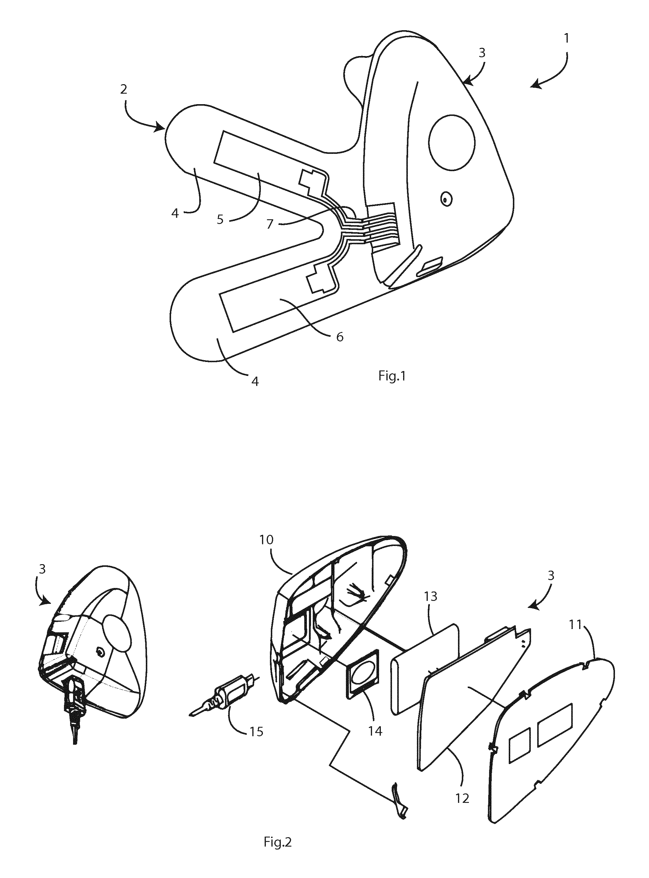
[0038]FIG. 1 is a perspective view of a sensor of a system of the invention,

[0039]FIG. 2 is an exploded view of a re-usable part,

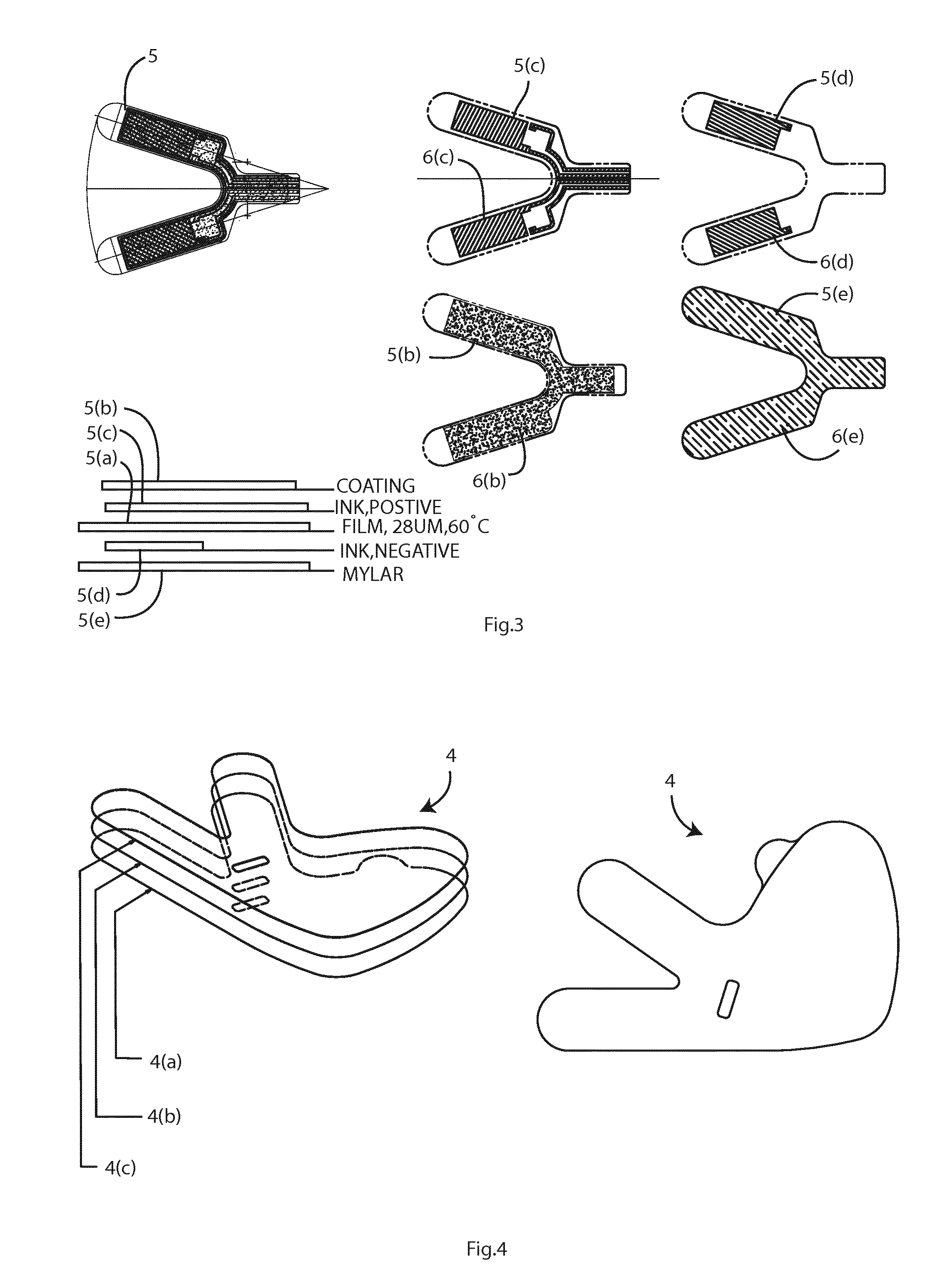
[0040]FIG. 3 is a set of views of layers of the transducers, and

[0041]FIG. 4 is an exploded perspective view of the layers of the sensor's substrate,

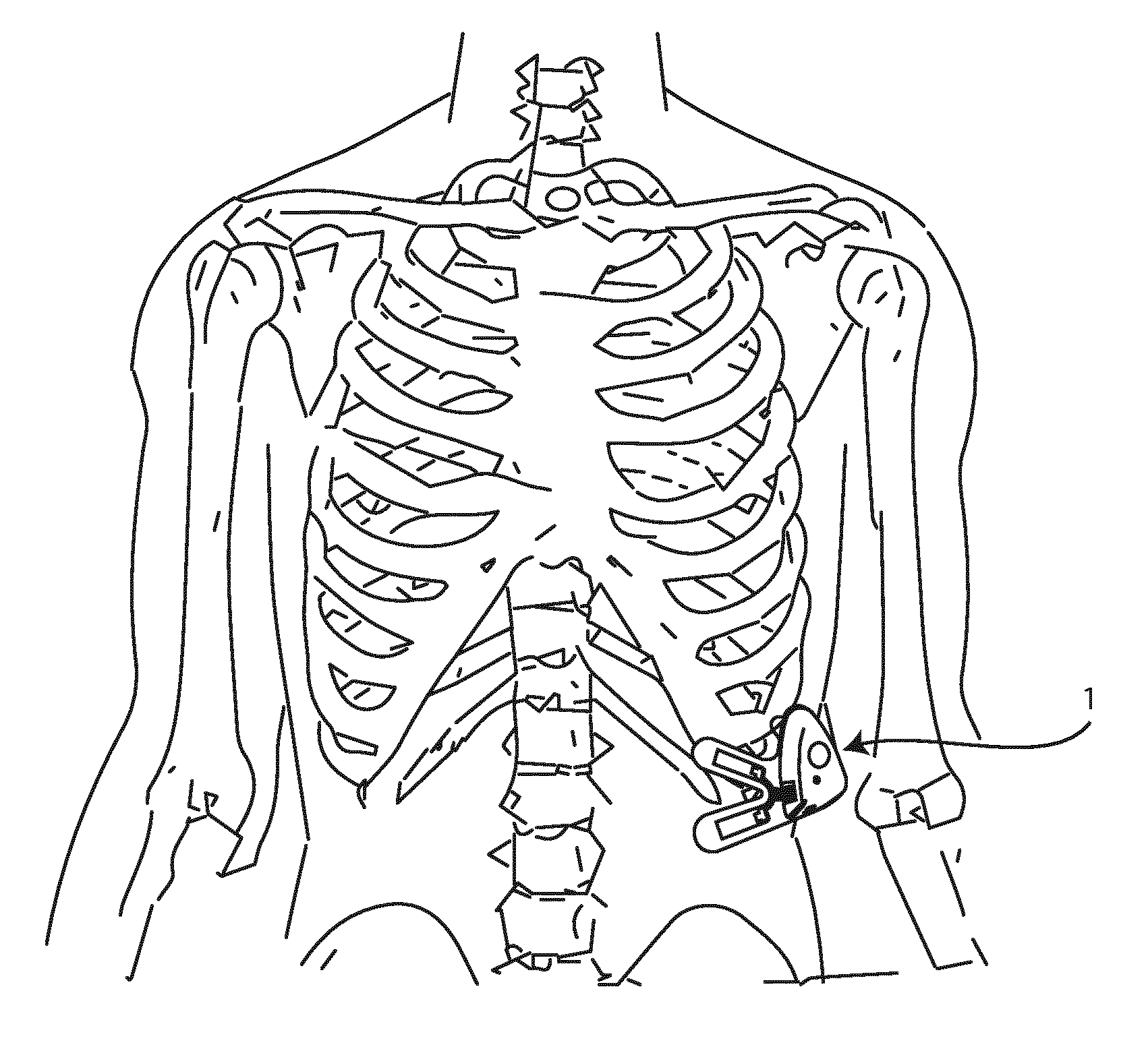
[0042]FIG. 5 is a diagram showing an optimal position for the sensor on the body;

[0043]FIG. 6 is a block diagram of the sensor system;

[0044]FIG. 7 shows an instrumental amplifier circuit to create a high common-mode rejection and high gain to eliminate any mutual environment interference and boost the signal for processing respectively for a single transducer;

[0045]FIG. 8 shows low pass filtering circuitry to produce a single output (per sensor) for digital signal processing, with high ...


PUM


Abstract

A respiration monitoring system has deformation transducers on a flexible substrate arranged to adhere to a patient's torso. A processor receives signals in channels from the transducers and processes them to eliminate, reduce or compensate for noise arising from patient motion artefacts, to provide an output representative of respiration. The transducers have a size and a mutual location on the substrate so that a first transducer can overlie at least part of the 10th rib and a second transducer can overlie at least part of the 11th rib or the abdomen, and the processor processes data from the first transducer as being primarily representative of rib distending respiration and from the second transducer as being primarily representative of either diaphragm respiration or patient motion artefacts.

Description

FIELD OF THE INVENTION[0001]The invention relates generally to devices useful in measuring and monitoring respiratory events in a human subject.PRIOR ART DISCUSSION[0002]Respiratory rate is the measure of the number of breaths a person has per minute and is a key vital sign in human subjects. Spirometry is the measure of lung capacity or lung volume in a human subject. Deterioration of these respiratory functions is the decline or increase of these measures. Measurements outside, or approaching the boundaries of, the predetermined physiological normal values are a pre-indicator to harmful and fatal emerging ailments in human subjects.[0003]Respiration is the process by which living organisms take in oxygen and convert it to energy. Part of this process is the mechanical inhalation of air which, for humans, is done via the nose and mouth. The mechanical respiratory effort is produced by the muscles of respiration. These muscles aid in both inspiration and expiration. The muscle group...

Claims


Application Information

Patent Timeline
Patent Type & Authority Applications(United States)
IPC IPC(8): A61B5/00A61B5/08G16H10/60
CPCA61B5/7207A61B5/7246A61B5/0816A61B5/0826A61B2562/164A61B5/6823A61B5/6833A61B2562/0219A61B2562/0261A61B5/7282A61B5/721A61B5/0022A61B5/0803A61B5/113A61B5/4818A61B5/7225A61B5/725A61B2560/0285A61B2560/0412A61B2560/0425A61B2560/045A61B2562/04A61B5/7257G16H40/67G16H20/40A61B5/746
Inventor MURRAY, MYLESCUSACK, STEPHENKINSELLA, CHRISTOPHER
Owner PMD DEVICE SOLUTIONS
Why Eureka
Try Eureka