Check patentability & draft patents in minutes with Patsnap Eureka AI!

Radio frequency peak detection with subthreshold biasing

a radio frequency peak and subthreshold biasing technology, applied in the field of radio frequency peak detection with subthreshold biasing, can solve the problems of high bit error rate, poor performance, and inability to detect the frequency of the signal input, and achieve the effect of avoiding the use of a relatively high signal input level, low power consumption, and low nois

Active Publication Date: 2016-01-07
INNOPHASE
View PDF0 Cites 2 Cited by
  • Summary
  • Abstract
  • Description
  • Claims
  • Application Information

AI Technical Summary

Benefits of technology

The solution achieves low power consumption and improved performance by enabling peak detection at lower signal amplitudes, reducing bit error rates and power consumption in wireless receiver applications.

Problems solved by technology

However, the proposed polar receiver architectures and associated signal processing have deficiencies that result in poor performance and high bit error rates (BER).
However, such detectors frequently require the use of a relatively high signal input level.
However, the use of an amplifier can lead to undesirably high levels of power consumption.

Method used


Image

  • Radio frequency peak detection with subthreshold biasing
  • Radio frequency peak detection with subthreshold biasing
  • Radio frequency peak detection with subthreshold biasing

Examples


Embodiment Construction

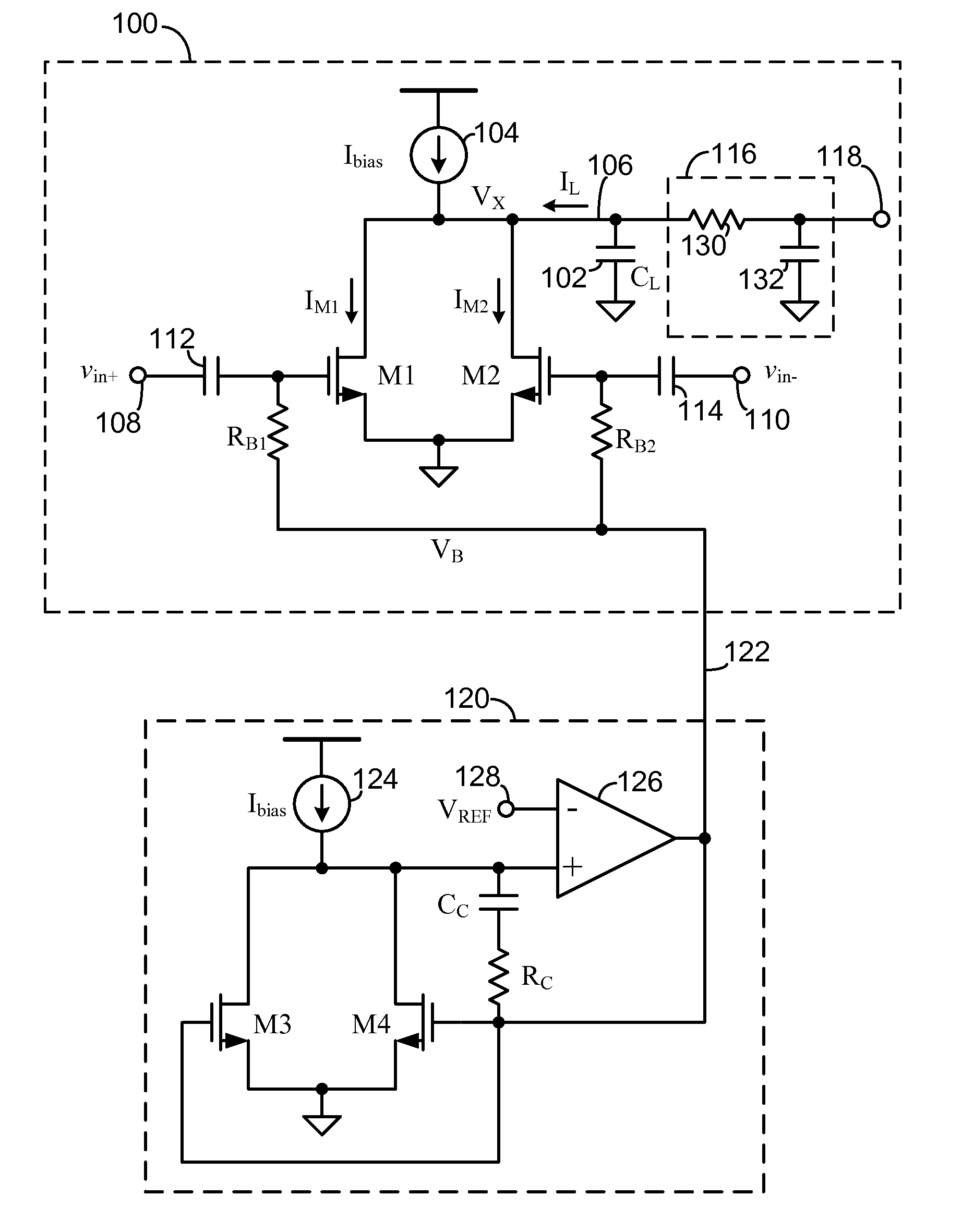
[0006]With reference to FIG. 1, a peak detection circuit 100 includes a load capacitor 102 with capacitance CL. The load capacitor 102 is connected between a common node 106 and ground. A current source 104 is connected to the common node 106 and operates to supply a current Ibias to charge the load capacitor 102 and set the correct bias current for transistors Ml and M2. The peak detection circuit 100 includes a first field effect transistor Ml and a second field effect transistor M2. The field effect transistors M1 and M2 may be insulated-gate transistors such as MOSFET transistors. Transistors M1 and M2 preferably have matched electrical characteristics and physical size. For example, transistors M1 and M2 preferably have substantially the same length and width, and same values of the threshold voltage Vth, and the slope factor n, where n=1+CD / COX, with CD being the capacitance of the depletion layer and Cox being the capacitance of the insulating layer.

[0007]The channels of tran...


PUM


Abstract

A radio-frequency peak amplitude detection circuit includes a load capacitor, a current source that charges the load capacitor and set the bias current for the field effect transistors, and a pair of field effect transistors. The gates of the field effect transistors are biased at a level below the threshold voltage of the transistors. The transistors are arranged in parallel with the capacitor and are operable to drain the capacitor at a rate determined by a differential input at the gates of the transistors. The voltage across the load capacitor is low-pass filtered and has a voltage level representative of the amplitude of the differential input signal.

Description

BACKGROUND OF THE INVENTION[0001]Communications transceivers may utilize numerous architectures to recover data from a modulated carrier signal. These architectures include coherent demodulation, using either intermediate frequency conversion or direct-conversion receivers. Such receivers typically recover or regenerate the communications carrier signal using a phase-locked loop (PLL) and coherent demodulation. Recently, polar receiver architectures have been proposed that extract the modulation phase components from a received modulated signal without using a carrier recovery circuitry. However, the proposed polar receiver architectures and associated signal processing have deficiencies that result in poor performance and high bit error rates (BER). Accordingly, there is a need for improved polar receiver signal processing and architectures.[0002]Various signal processing architectures often make use of peak detectors to measure the peak level of a radio frequency signal. However, ...

Claims


Application Information

Patent Timeline
Patent Type & Authority Applications(United States)
IPC IPC(8): G05F1/46H03H11/04H03K3/012
CPCG05F1/46H03K3/012H03H11/04
Inventor TESTI, NICOLOLI, XIXU, YANG
Owner INNOPHASE
Features
  • R&D
  • Intellectual Property
  • Life Sciences
  • Materials
  • Tech Scout
  • Unparalleled Data Quality
  • Higher Quality Content
  • 60% Fewer Hallucinations
Learn More