Measurement probe with heat cycle event counter

a technology of event counter and measurement probe, which is applied in the direction of heat measurement, force/torque/work measurement apparatus, instruments, etc., can solve the problems of high sterilization of the entire probe body, sensor failure, and health risks

Active Publication Date: 2016-01-07
BROADLEY JAMES
View PDF6 Cites 66 Cited by
  • Summary
  • Abstract
  • Description
  • Claims
  • Application Information

AI Technical Summary

Benefits of technology

[0010]The present disclosure describes devices and methods used to detect and count heat cycles experienced by measurement probes, particularly heat cycles associated with steam heat sterilization and hot chemical solution cleaning procedures. These procedures are among the greatest contributors to probe degradation an...

Problems solved by technology

This may be because bacteria and other microorganisms may proliferate on unsterilized surfaces and create health risks.
Additionally, sterilization or cleaning of bioprocess vessels or pipes in which sensors are installed can expose the sensors to high temperatures and/or harsh chemicals that can introduce errors in the sensor's measurement signal or even lead to sensor failure.
The major drawback to autoclaving is that the entire probe body is subjected to the high sterilization temperature and this can have a detrimental effect on any internal circuitry that is powered up at the time.
Measurement probes can experience structural changes, aging, and decreased functionality and accuracy through exposure to extreme conditions.
Particularly, the rapid increase and decrease of temperature associated with common steam heat sterilization or hot chemical solution ...

Method used


Image

  • Measurement probe with heat cycle event counter
  • Measurement probe with heat cycle event counter
  • Measurement probe with heat cycle event counter

Examples


Embodiment Construction

[0056]In the following detailed description, reference is made to the accompanying drawings, which form a part of the present disclosure. The illustrative embodiments described in the detailed description, drawings, and claims are not meant to be limiting. Other embodiments may be utilized, and other changes may be made, without departing from the spirit or scope of the subject matter presented here. It will be readily understood that the aspects of the present disclosure, as generally described herein, and illustrated in the Figures, can be arranged, substituted, combined, and designed in a wide variety of different configurations, all of which are explicitly contemplated and form part of this disclosure.

[0057]The terminology used herein is for the purpose of describing particular embodiments only and is not intended to be limiting of the disclosure. It will be understood by those within the art that if a specific number of a claim element is intended, such intent will be explicitl...


PUM


Abstract

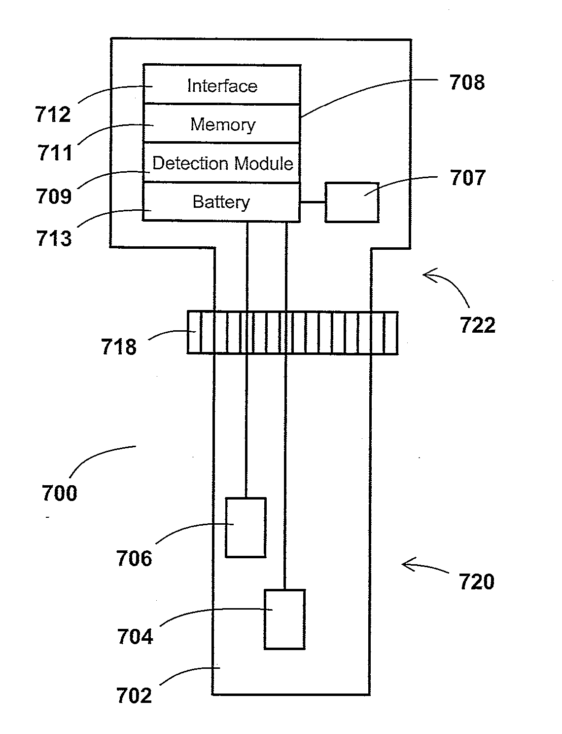
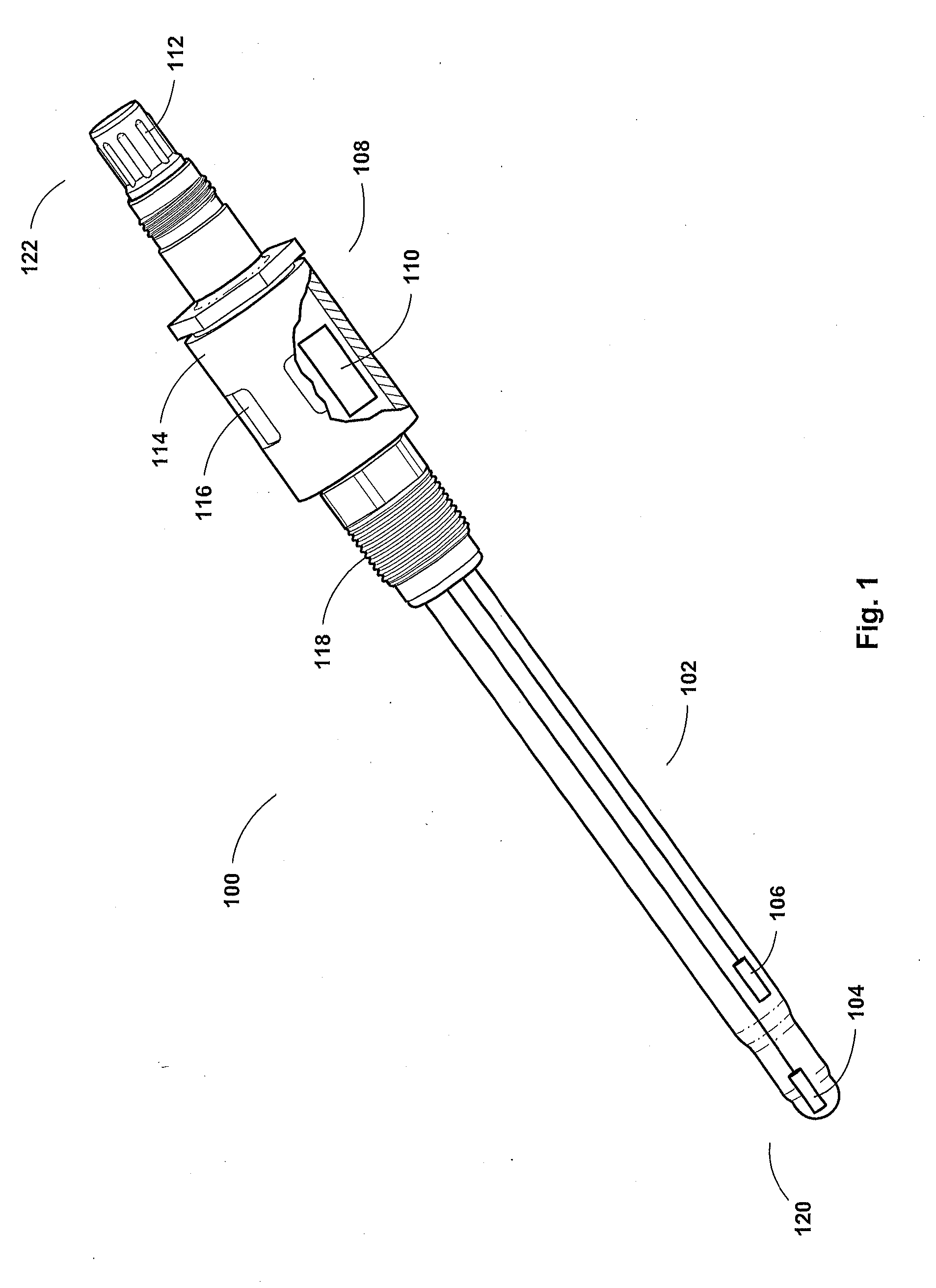
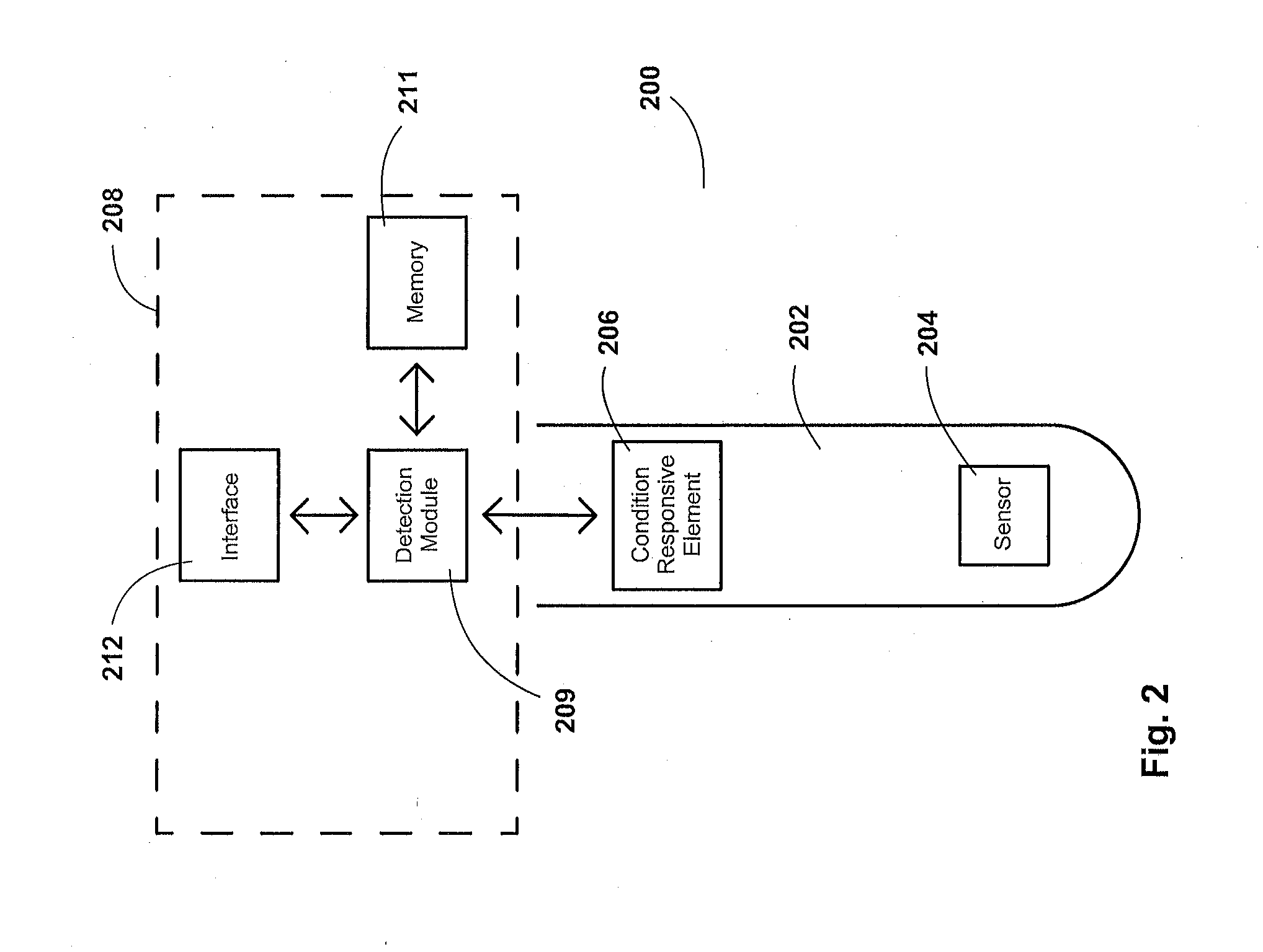
A system comprising a measurement device and a handheld device is disclosed, the system adapted to withstand, detect, record, and display heat cycle event counts. The measurement device comprises a sensor for measuring and a heat cycle detection unit. The heat cycle detection unit comprises a temperature or pressure responsive element, a detection module, data interface, and data memory. The handheld device comprises a screen, a button, a communication circuit, and a processing system. The communication circuit is configured to communicate with the measurement device and a computing device and the processing system is configured to receive non-measurement information from the measurement device, display the received information on the screen, and cycle the received information displayed on the screen based on an actuation of the button, wherein the handheld device is used to display a heat sterilization cycle count of the measurement device.

Description

CROSS-REFERENCES TO RELATED APPLICATIONS[0001]This application is a continuation-in-part of U.S. patent application Ser. No. 14 / 801,625, filed Jul. 16, 2015, which is a continuation of U.S. patent application Ser. No. 14 / 207,347, filed Mar. 12, 2014, granted as U.S. Pat. No. 9,117,166, on Aug. 25, 2015, which claims priority benefit of U.S. Provisional Application No. 61 / 794,355, filed Mar. 15, 2013; this application is a continuation-in-part of Patent Cooperation Treaty Application No. PCT / US2014 / 025025, filed Mar. 12, 2014, which claims priority benefit of U.S. Provisional Application No. 61 / 794,355, filed Mar. 15, 2013; each of the aforementioned applications are incorporated by reference in its entirety herein.BACKGROUND[0002]1. Field of the Invention[0003]The present invention relates to measurement probes. More particularly, the invention relates to devices and methods used to detect and count heat cycles experienced by measurement probes.[0004]2. Description of the Related Ar...

Claims


Application Information

Patent Timeline
IPC IPC(8): G06M1/10A61L2/07G01K13/00G01L5/00H02J7/00
CPCG06M1/10H02J7/0052H02J7/345G01L5/00A61L2/07G01K13/00G01L19/0092G01L23/32G07C3/00G06M1/02H02J7/342H02J50/10A61L2202/14G01K13/02
Inventor REYNOLDS, WILLIAM E.GARRAHY, ROBERT J.HAYWARD, ANDREW W.FISH, ROBERTNATHANSON, JARED H.SARGENT, BRADLEY JOSEPHBROADLEY, SCOTT T.
Owner BROADLEY JAMES
Why Eureka
Try Eureka