Supercharge Your Innovation With Domain-Expert AI Agents!

Waveguide-type image rejection filter and single-sideband receiver, frequency divider, and sideband-separating receiver using the same filter

a filter and waveguide technology, applied in the direction of electrical equipment, transmission, coupling devices, etc., can solve the problems of difficult to amplify electromagnetic waves, rare availability of amplification equipment, etc., and achieve the effect of suppressing characteristic degradation, convenient processing, and suitable for mass production

Active Publication Date: 2016-01-07
OSAKA PREFECTURE UNIV PUBLIC CORP
View PDF4 Cites 2 Cited by
  • Summary
  • Abstract
  • Description
  • Claims
  • Application Information

AI Technical Summary

Benefits of technology

This patent describes various filters and receivers for improving image rejection in electronic devices. The filters use 90-degree hybrid couplers, band pass filters, and radiowave absorptive terminations, which can be easily processed and are suitable for mass production. The filters help to suppress unwanted reflections that can degrade image quality. The receivers use the filters and couplers to achieve a large sideband ratio and minimize changes over time. The frequency divider is a simplified version of a more complex circuit, which can also be easily processed and retained its characteristics over long periods of time. Overall, this patent provides technical solutions for improving image quality in electronic devices.

Problems solved by technology

It, however, is not easy to amplify the electromagnetic waves because noise from a receiver reaches a considerable level for signal processing.
In addition, amplification equipment is rarely available, that may directly amplify the waves at frequency bands called millimeter and submillimeter bands.

Method used


Image

  • Waveguide-type image rejection filter and single-sideband receiver, frequency divider, and sideband-separating receiver using the same filter
  • Waveguide-type image rejection filter and single-sideband receiver, frequency divider, and sideband-separating receiver using the same filter
  • Waveguide-type image rejection filter and single-sideband receiver, frequency divider, and sideband-separating receiver using the same filter

Examples


embodiment 1

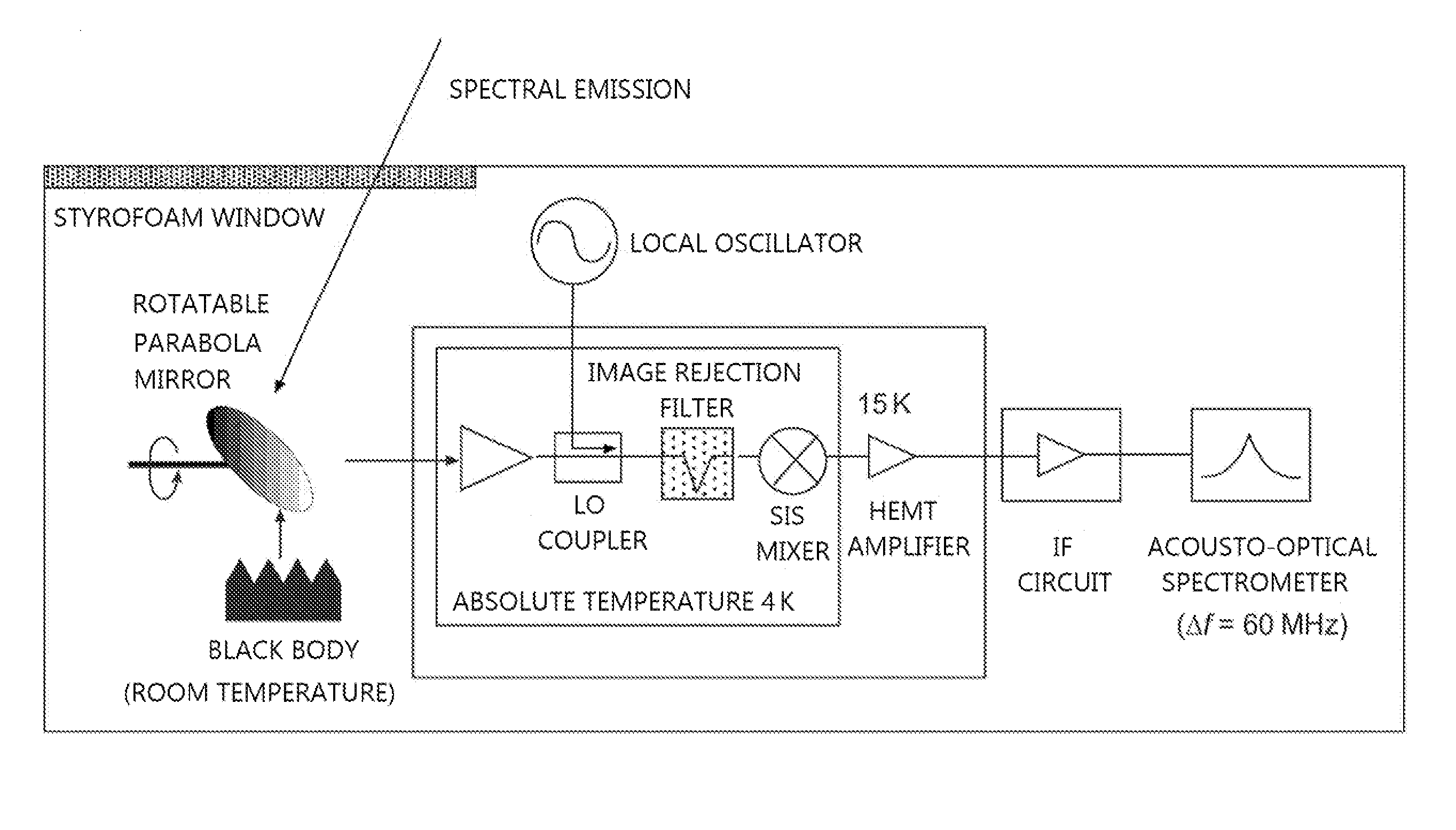
[0067]The inventors of the present invention arrived at an idea of the structures of this invention different from traditional image rejection filters that reflect electromagnetic waves within a rejection band by using a resonator. Namely, the image rejection filter of this invention is capable of suppressing reflections by guiding only electromagnetic waves within a band that should be intercepted to a radiowave absorber.

Structural Components of Image Rejection Filter and How the Components are Connected

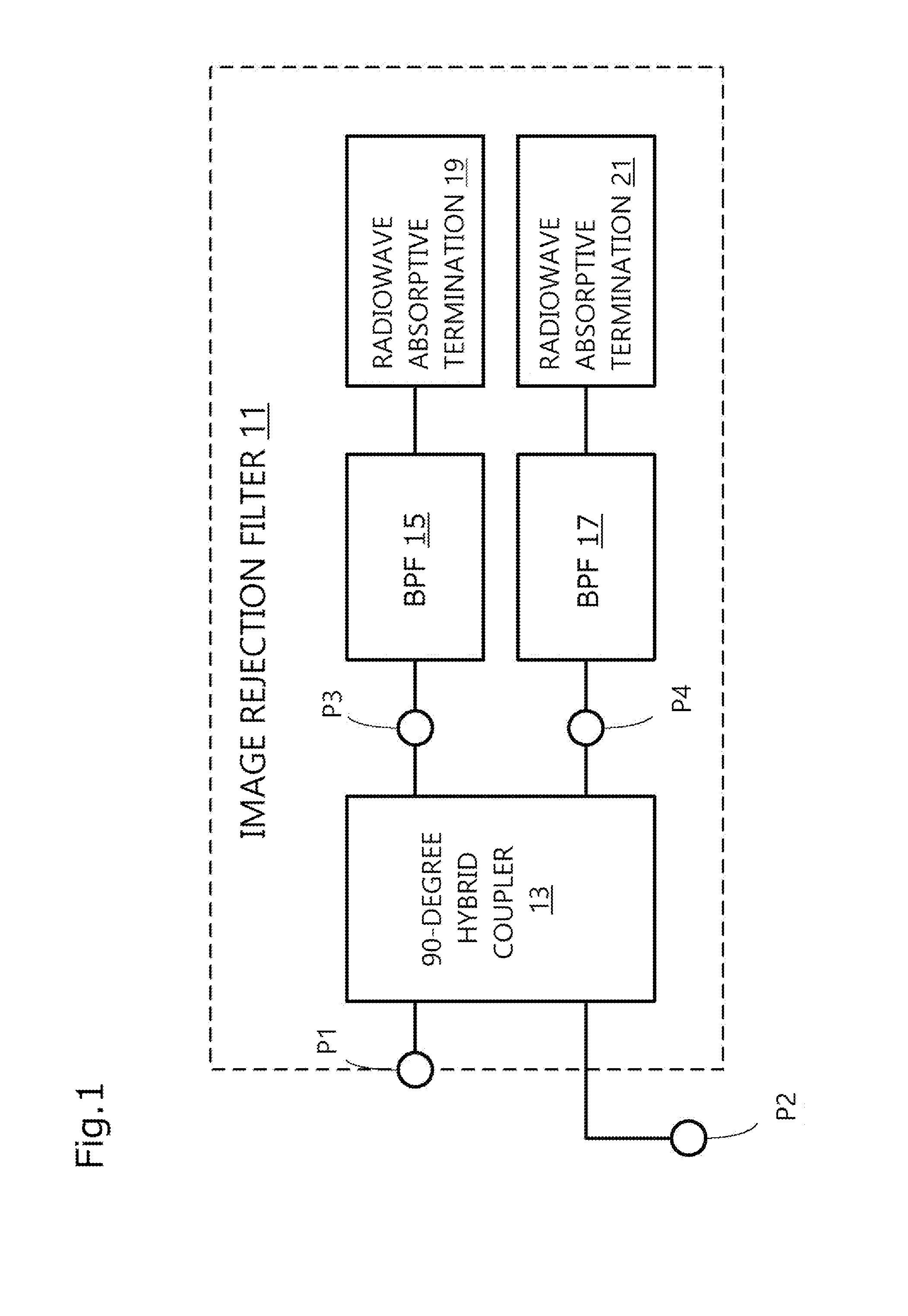
[0068]FIG. 1 is a block diagram indicating structural components of an image rejection filter of this invention and how the components are connected. As seen in FIG. 1, an image rejection filter 11 comprises the following three main components:

[0069]i) a waveguide-type 90-degree hybrid coupler (indicated by a reference numeral 13 in FIG. 1)

[0070]ii) waveguide-type band pass filters (indicated as BPF 15 and BPF 17, respectively, in FIG. 1)

[0071]iii) radiowave absorptive terminations...

embodiment 2

[0122]In Embodiment 2, a single-sideband receiver will be explained, that comprises the image rejection filter of Embodiment 1.

[0123]A traditional system using a Martin-Puplett-type frequency filter has problems such as repeatability and secular changes because this system has a movable part. A 2-backshort system also has a problem about reliability because a sideband ratio changes according to tuning of two mixers. These traditional systems share the same problem such that a sideband ratio is only on the order of 10 to 20 dB to use a phase difference, etc.

[0124]A single-sideband receiver of this Embodiment is categorized into a system capable of filtering the image side by using a waveguide-type image rejection filter. The waveguide-type image rejection filter enables the system to be downsized and simplified. The traditional waveguide-type image rejection filters reflect wave within a rejection band instead of letting them pass, and this results in standing waves caused by the ref...

embodiment 3

[0139]In Embodiment 3, a frequency divider will be explained, that is converted from the image rejection filter of Embodiment 1 as a modified example.

[0140]In recent years, there have been technical advances toward millimeter and submillimeter bands; and waveguides that are low in loss have been increasingly desired as transmission lines. Reason for this is that the millimeter and the submillimeter bands are impractical because these bands lose a significant amount of electric power at a dielectric body in a plane substrate circuit or a dielectric laminated circuit. The waveguides, however, are more difficult as solid circuit components than the plane substrate circuit or the dielectric laminated circuit to prepare the frequency divider.

[0141]FIG. 10 is a block diagram indicating a basic structure of a waveguide-type frequency divider of this Embodiment. A basic block 50 comprises the following components:

[0142]i) waveguide-type 90-degree hybrid couplers (indicated by reference nume...


PUM


Abstract

An image rejection filter comprising a waveguide-type 90-degree hybrid coupler having an input port for receiving an input signal within a millimeter or submillimeter band, first and second output ports for dividing the input signal in two and outputting the divided signals, respectively, wherein the one signal deviates by a 90-degree phase from the other signal, and a branch port for outputting the signal; a pair of band pass filters: a waveguide-type first band pass filter whose one end is connected with the first output port and a waveguide-type second band pass filter whose one end is connected with the second output port; and a pair of radiowave absorptive terminations: a first radiowave absorptive termination connected to the other end of the first band pass filter and a second radiowave absorptive termination connected to the other end of the second band pass filter.

Description

TECHNICAL FIELD[0001]This invention relates to a waveguide-type image rejection filter and a single-sideband receiver, a frequency divider, and a sideband-separating receiver using the same filter.BACKGROUND ART[0002]A heterodyne receiving system has been known, that receives spectra from astronomical objects and atmospheric minor molecules.[0003]For example, it is on its way to becoming assured as a result of recent research efforts that rarefied interstellar materials including gases and dusts give a birth of a star; and the rarefied interstellar materials emit electromagnetic waves within a millimeter or submillimeter band of oscillation frequencies fixed by every molecular species associated with rotating motions of molecules of the interstellar materials. These electromagnetic waves are observed so as to achieve research outcomes with respect to birth and evolution of stars. Known as equipment for observing the electromagnetic waves are radio telescopes.[0004]To observe, for ex...

Claims


Application Information

Patent Timeline
IPC IPC(8): H01P5/16H01P1/213H04B1/16
CPCH01P1/213H04B1/16H01P5/16H01P1/208H01P1/2138
Inventor HASEGAWA, YUTAKAOGAWA, HIDEOASAYAMA, SHIN'ICHIRO
Owner OSAKA PREFECTURE UNIV PUBLIC CORP
Features
  • R&D
  • Intellectual Property
  • Life Sciences
  • Materials
  • Tech Scout
  • Unparalleled Data Quality
  • Higher Quality Content
  • 60% Fewer Hallucinations
Learn More