
Online uninterruptible power supply topology

a power supply and topology technology, applied in the field of switching power supplies, can solve the problems of limited operation conditions and difficulty in further improving the overall conversion efficiency of this mode, and achieve the effect of high-efficiency operation

Active Publication Date: 2016-01-07
EATON INTELLIGENT POWER LIMITED
View PDF8 Cites 33 Cited by
  • Summary
  • Abstract
  • Description
  • Claims
  • Application Information

AI Technical Summary

Benefits of technology

The present invention provides a novel online UPS topology and control methods to improve conversion efficiency. The UPS operates in four modes: high-efficiency operation mode, double conversion mode, battery mode, and bypass mode. The high-efficiency operation mode is unique to the present invention and allows for seamless switching between different modes without interrupting output. The technical effects of the present invention include improved conversion efficiency, faster switching between modes, and seamless output.

Problems solved by technology

Due to presence of the two-stage power conversion, limited by the existing semiconductor and magnetic material technology, it is difficult to further improve the overall conversion efficiency.
Although such UPS topology comprises a highly-efficient bypass mode of opening a bypass switch and closing a power conversion stage, yet operation conditions of this mode are limited by many factors, which is too dependent on the quality of the input power of the grid.

Method used


Image

  • Online uninterruptible power supply topology
  • Online uninterruptible power supply topology
  • Online uninterruptible power supply topology

Examples


Embodiment Construction

[0031]The preferred embodiments for implementing the present invention will be introduced with reference to the accompanying drawings.

[0032]FIG. 3 and FIG. 4 respectively illustrate topologies of a three-phase and a single-phase online UPS according to the embodiments of the present invention. For simplicity, hereinafter, application will be introduced for the single-phase UPS; however, all the results are equally applicable to applications of the three-phase or the two-phase UPS.

[0033]As shown in FIG. 4, the single-phase online uninterruptible power supply topology may comprise a main power circuit, an auxiliary power circuit and a bypass circuit as optional. The main power circuit consists of an input stage, a power conversion stage, and an output stage connected successively. The input stage of the main power circuit includes a first capacitor C1 and a first inductor L1. The power conversion stage of the main power circuit includes first to fourth series branches connected in par...


PUM


Abstract

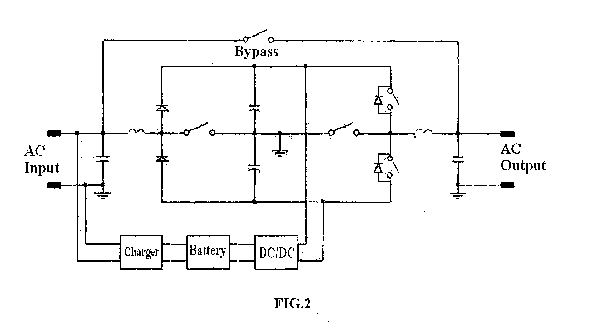
The present invention relates to an online uninterruptible power supply topology. A single-phase topology comprises a main circuit and an auxiliary circuit. A power conversion stage of the main power circuit includes first to fourth branches connected in parallel between a positive bus and a negative bus, the first branch consists of a first diode and a second diode connected in series, the second branch consists of a second capacitor and a third capacitor connected in series, and a first switch is connected between the intermediate node of the first branch and the intermediate node of the second branch, the third branch consists of a third switch, a fifth capacitor, a sixth capacitor, a fourth switch connected in series, the intermediate node of the second branch together with a node between the fifth capacitor and the sixth capacitor are connected to ground, the fourth branch consists of a fifth switch and a sixth switch connected in series, the second switch is connected between the intermediate node of the second branch and the intermediate node of the fourth branch, and the third switch and the fourth switch respectively have a third diode and a fourth diode connected in parallel. An input of the charger of the auxiliary circuit is connected to an AC input or positive and negative buses of the uninterruptible power supply, an output of the DC / DC converter is connected to a node between the third switch and the fifth capacitor and a node between the sixth capacitor and the fourth switch.

Description

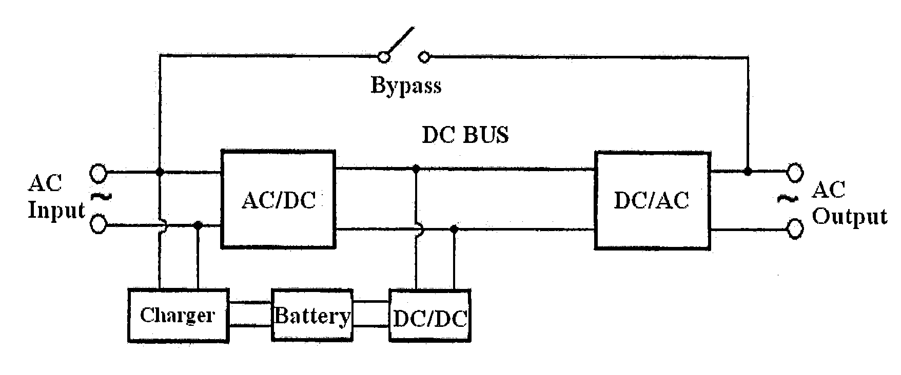
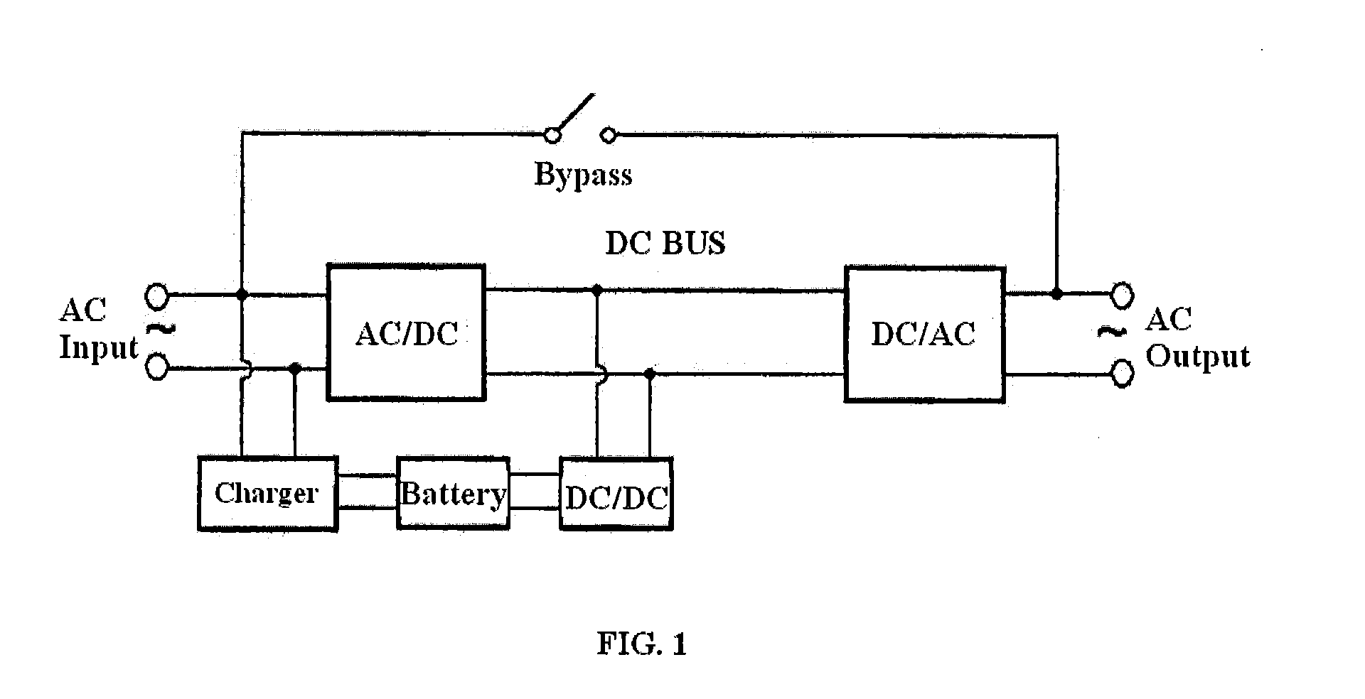
TECHNICAL FIELD[0001]The present invention relates to the field of switching power supply, and more particularly, relates to an online uninterruptible power supply (UPS).BACKGROUND[0002]An uninterruptible power supply (UPS) is a power supply apparatus for providing a load with uninterrupted, high-quality, reliable AC power, and having functions of protecting and monitoring the state of power supply in real time, which plays an important role in improving quality of power supply and ensuring normal operation of an apparatus. From perspectives of the circuit structure and mode of uninterrupted power supply, the UPS is mainly divided into two categories of a back-up type and an online type.[0003]FIG. 1 exemplarily shows a configuration block diagram of a conventional online UPS. When the power of the grid is normal, an input AC voltage is converted into a DC voltage after rectified and filtered, to directly drive an inverter to power a load, while charging the battery. The inverter out...

Claims


Application Information

Patent Timeline
IPC IPC(8): H02J9/06H02M3/04H02M5/42
CPCH02J9/06H02M5/42H02M3/04H02J3/01H02J7/34H02J9/062H02J9/063H02M5/458H02M7/487Y02E40/40
Inventor YANG, YUEFENGGU, YILEILI, YUEHUI
Owner EATON INTELLIGENT POWER LIMITED
Learn More