Puncture planning apparatus and puncture system

a technology of puncture planning and planning apparatus, which is applied in the direction of instruments, applications, ultrasonic/sonic/infrasonic diagnostics, etc., can solve the problems of difficulty in sufficiently correcting puncture errors, and achieve the effect of minimizing puncture errors and minimizing errors

Active Publication Date: 2016-01-14
CANON KK
View PDF1 Cites 26 Cited by
  • Summary
  • Abstract
  • Description
  • Claims
  • Application Information

AI Technical Summary

Benefits of technology

[0010]If the organ is punctured in a state where the path of the needle and the target segment deviate from each other and the needle enters into the organ, it is difficult to sufficiently correct puncture error by the path correction in stage (3) alone. Moreover, the path correction in stage (3) should be minimal since healthy tissue inside the organ may be damaged. Therefore it is preferable to correct the path of the needle (e.g. angle) during stage (2), that is, before the needle punctures and enters the organ, so as to minimize puncture error due to deformation of the organ.
[0011]With the foregoing in view, it is an object of the present invention to provide a technique to plan the puncture operation that can minimize an error generated when the needle is inserted into the organ.

Problems solved by technology

If the organ is punctured in a state where the path of the needle and the target segment deviate from each other and the needle enters into the organ, it is difficult to sufficiently correct puncture error by the path correction in stage (3) alone.

Method used


Image

  • Puncture planning apparatus and puncture system
  • Puncture planning apparatus and puncture system
  • Puncture planning apparatus and puncture system

Examples


embodiment 1

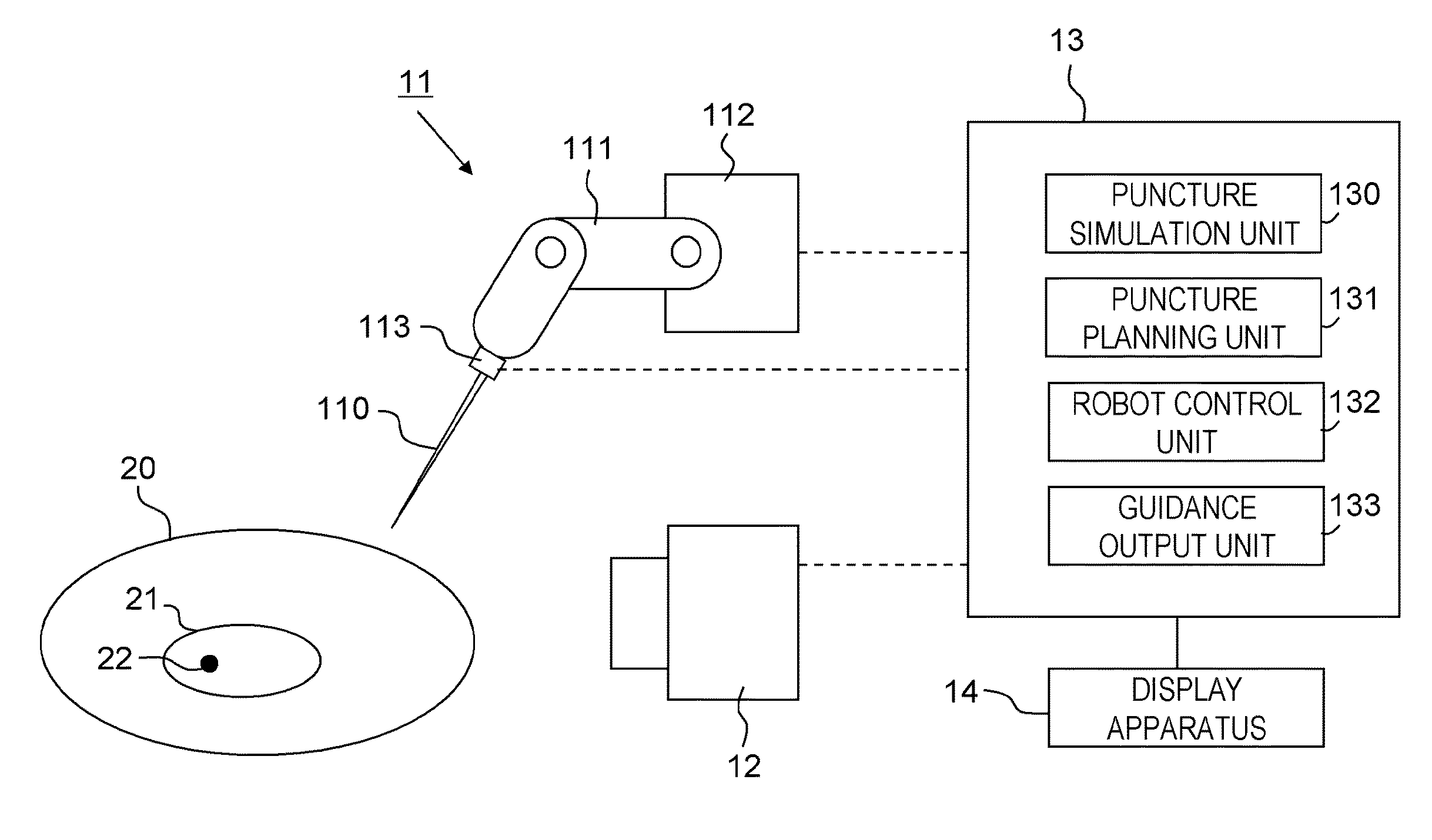
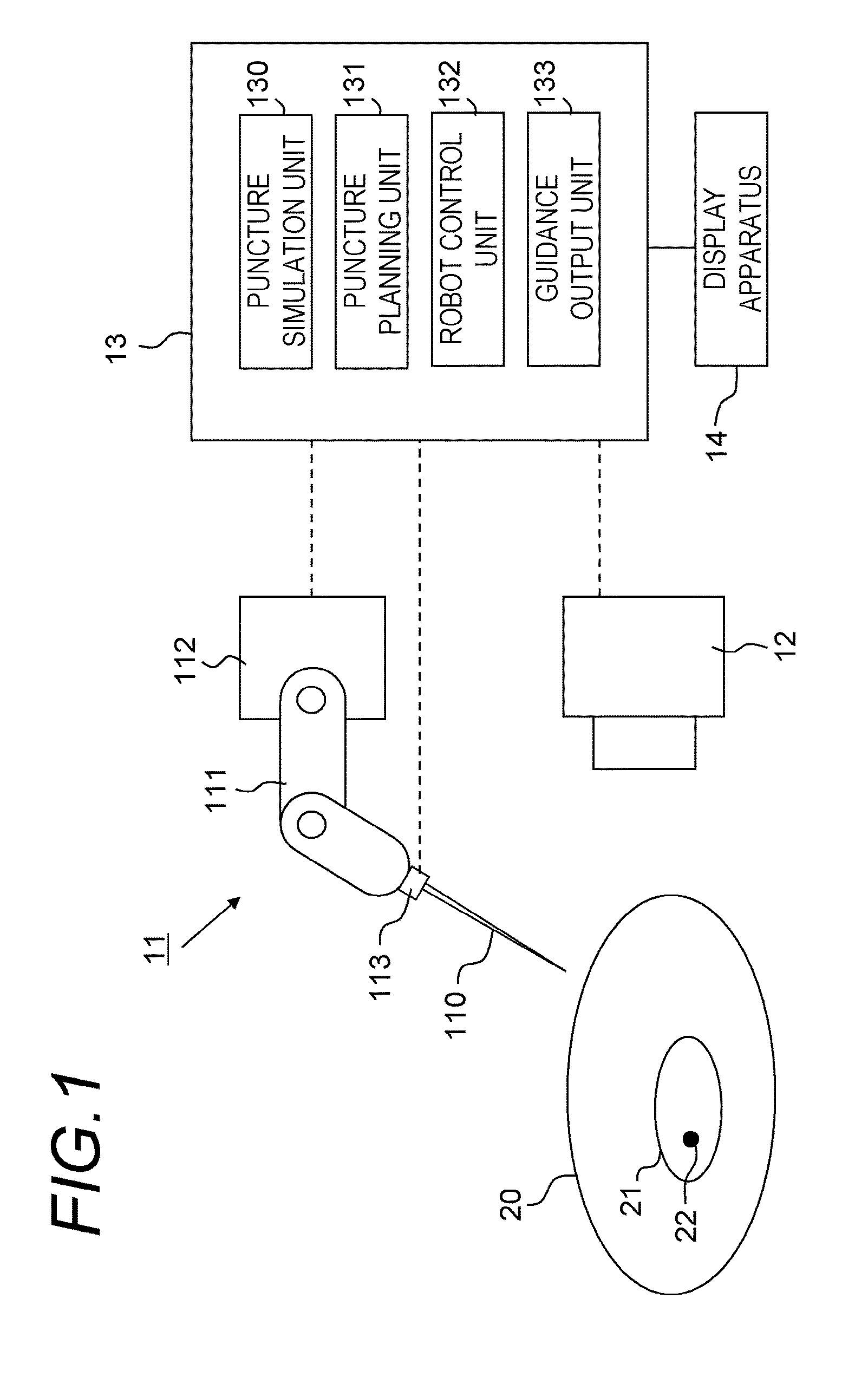
[0070]Functions of the puncture simulation unit 130 and the puncture planning unit 131 of the puncture control apparatus 13 will now be described in detail.

[0071](Puncture Simulation and Planning)

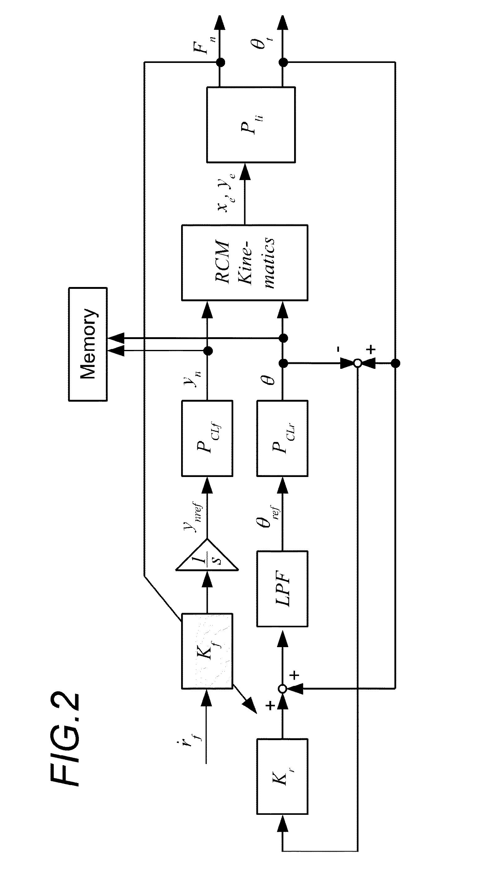
[0072]FIG. 2 is a block diagram depicting a control system of a puncture robot used for the puncture simulation.

[0073]Here Pli is a model of an organ (liver in this embodiment). PCLf is a model of a servo system to move the needle held by the robot forward or backward, and has an internal feedback loop to follow the movement of the needle based on a needle advancement target displacement ynref as a reference signal, and the control output thereof becomes the needle advancement displacement yn. The control system is further characterized in that the needle advancement speed is continuously changed in accordance with the puncture reaction force Fn in order to improve the puncture accuracy. The puncture reaction force refers to the reaction force that the puncture needle receives when the punc...

embodiment 2

[0103]FIG. 9A shows a block diagram depicting a control system of a puncture robot used for the puncture simulation, as another embodiment of the functions of the puncture simulation unit 130 and the puncture planning unit 131 of the puncture control apparatus 13. Here, just like Embodiment 1, Pli is a model of an organ (liver in this embodiment). PCL has the models PCLf and PCLr of the servo system of Embodiment 1, which are combined in parallel. PCL has an internal feedback loop that follows the needle advancement target displacement ynref and the needle target angle θref as the reference signals. The control outputs of PCL become the needle advancement displacement yn and the needle angle θ. Just like embodiment 1, Fn denotes the puncture reaction force, and θt denotes the target angle.

[0104]In this embodiment, the simulation is performed using a control system that has three types of reference signals: ref1, ref2 and ref3, for the needle advancement displacement and the needle a...


PUM


Abstract

A puncture planning apparatus has: a simulation unit that simulates movement of an organ and a puncture needle by simulation using an organ model; and a planning unit that plans, based on the simulation result, how to move the puncture needle when an actual organ is punctured. The simulation unit executes a plurality of times of the simulation of an operation to advance the puncture needle while correcting an angle of the puncture needle so as to follow the movement of the target segment due to deformation of the organ, conditions of an advancement speed of the puncture needle are changed for each of the plurality times of the simulation, and the planning unit performs planning using the best simulation result out of the plurality of simulation results acquired under different conditions of the advancement speed.

Description

BACKGROUND OF THE INVENTION[0001]1. Field of the Invention[0002]The present invention relates to a technique to perform planning for puncture.[0003]2. Description of the Related Art[0004]Minimal invasive treatment is an effective treatment method, which exerts minimal physical burden on a patient and can reduce post operative medical treatment and decrease a rehabilitation period, and is advantageous in terms of reducing medical cost. A minimal invasive percutaneous treatment method that is attracting attention is a localized treatment, where a puncture needle is inserted into an organ from outside the body, and a radio wave, a microwave, a laser or the like is irradiated causing necrosis of tumor tissue.[0005]In the puncture treatment, it is demanded that the puncture needle is accurately inserted so that the tip of the puncture needle reaches a target segment, such as a tumor. For this reason, puncture is normally performed while checking the position of the target, such as a tumo...

Claims


Application Information

Patent Timeline
Patent Type & Authority Applications(United States)
IPC IPC(8): A61B17/34G06F17/10G16Z99/00
CPCA61B19/50A61B17/3403A61B19/2203A61B2017/3405G06F17/10A61B2019/504A61B2019/507G06F19/3437A61B2034/104A61B34/30A61B34/10A61B2034/107A61B2017/3413G16H50/50G16Z99/00A61B8/0841A61B17/3478A61B90/11A61B5/065A61B34/20G01R33/287G06F30/00
Inventor TAKAGI, KIYOSHI
Owner CANON KK
Why Eureka
Try Eureka