Closed loop drilling mud cooling system for land-based drilling operations

a cooling system and closed-loop technology, applied in the direction of insulation, chemistry apparatus and processes, borehole/well accessories, etc., can solve the problems of premature equipment failure, high cost of drilling mud in general, and the addition of solid particles in particular, so as to reduce the flow temperature and reduce the flow temperature

Active Publication Date: 2016-01-14
NAT OILWELL VARCO LP
View PDF4 Cites 6 Cited by
  • Summary
  • Abstract
  • Description
  • Claims
  • Application Information

AI Technical Summary

Benefits of technology

[0021]The following presents a simplified summary of the present disclosure in order to provide a basic understanding of some aspects disclosed herein. This summary is not an exhaustive overview of the disclosure, nor is it intended to identify key or critical elements of the subject matter disclosed here. Its sole purpose is to present some concepts in a simplified form as a prelude to the more detailed description that is discussed later.
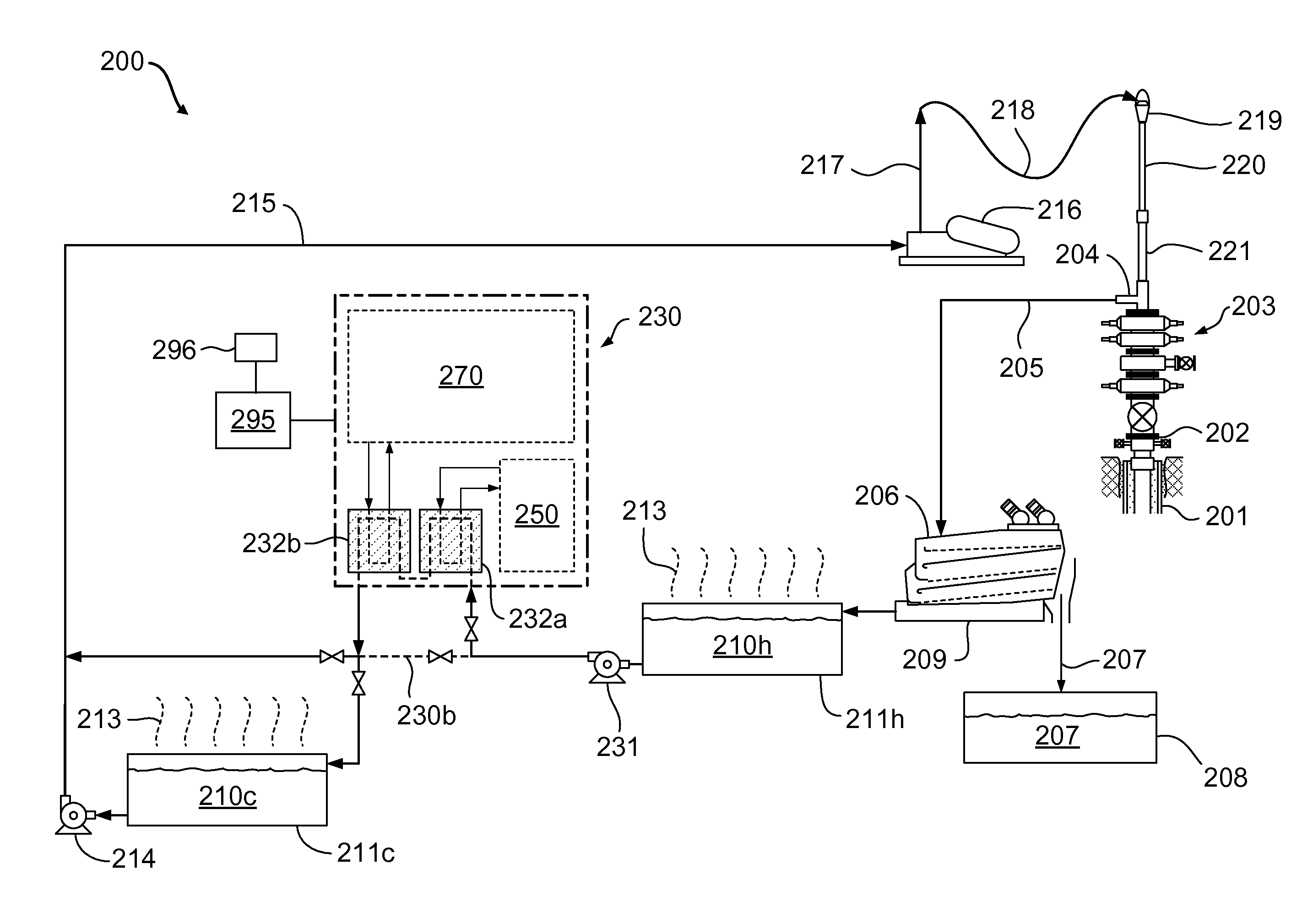
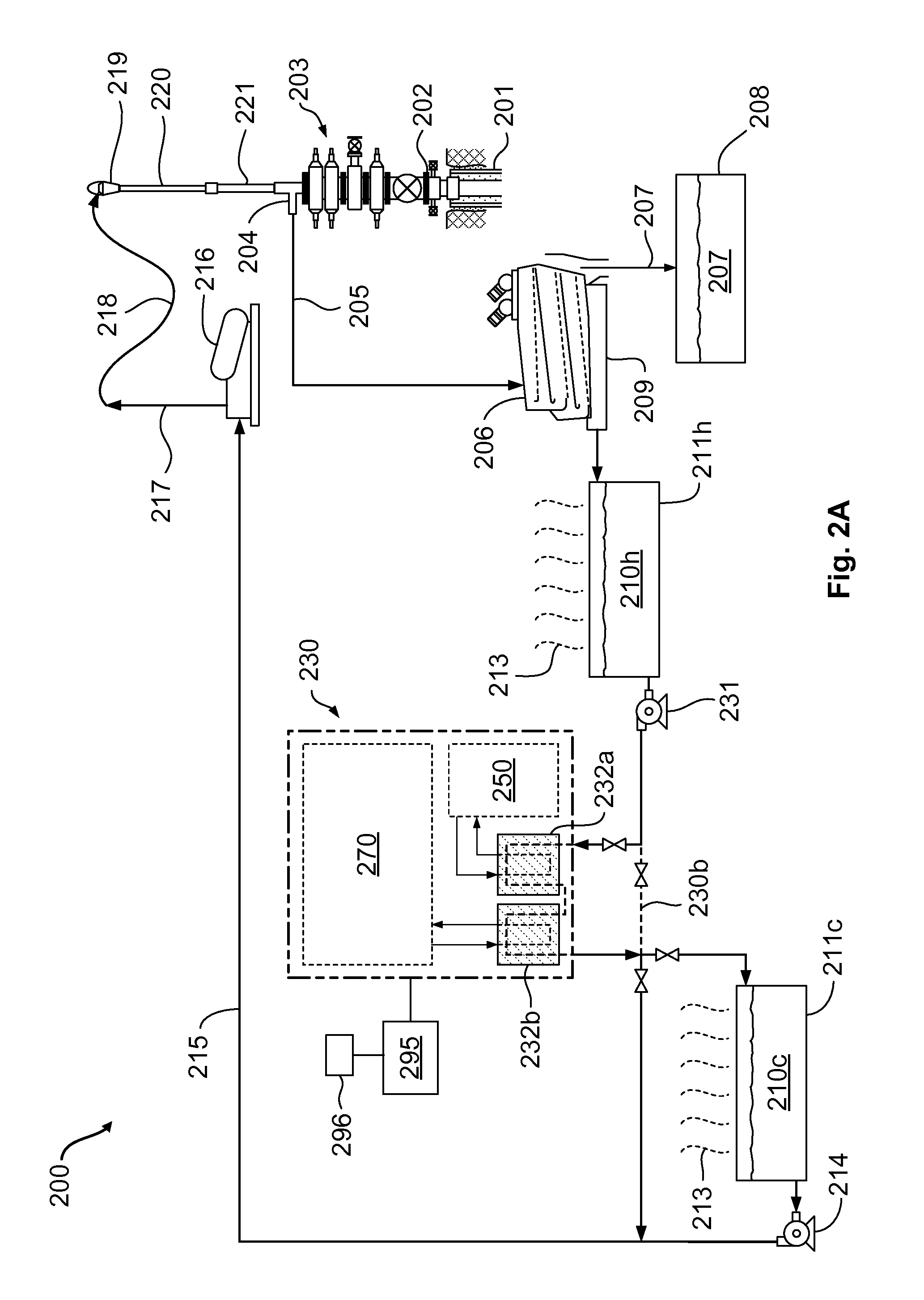
[0022]Generally, the subject matter disclosed herein is directed to various new and unique systems, apparatuses, and methods for circulating and cooling drilling mud during wellbore drilling operations, and in particular, for high temperature drilling operations in onshore applications. In one illustrative embodiment, a drilling mud cooler is disclosed that includes, among other things, a first mud heat exchanger that is adapted to receive a flow of drilling mud and a first closed-loop cooling system that is adapted to cool a first cooling fluid that is circulated through the first mud heat exchanger so as to reduce a temperature of the flow of drilling mud from a first temperature to a second temperature. The disclosed drilling mud cooler further includes a second mud heat exchanger that is adapted to receive the flow of reduced temperature drilling mud from the first mud heat exchanger and a second closed-loop cooling system that is adapted to cool a second cooling fluid that is circulated through the second mud heat exchanger so as to further reduce the temperature of the flow of drilling mud from the second temperature to a third temperature.
[0023]In another illustrative embodiment, a system for cooling drilling mud is disclosed that includes a drilling mud cooler having first and second stage closed-loop cooling systems that are thermally coupled to respective first and second stage mud heat exchangers, wherein the drilling mud cooler is adapted to receive a flow of drilling mud having a first mud temperature into the first stage mud heat exchanger and to discharge the flow of drilling mud from the second stage mud heat exchanger at a second temperature that is less than the first temperature. The illustrative drilling mud cooling system further includes, among other things, a control system that is operatively coupled to the drilling mud cooler, wherein the control system is adapted to sequentially stage operation of the first and second stage closed-loop cooling systems by initiating operation of the first stage closed-loop cooling system so as to cool the flow of drilling mud flowing through the first stage mud heat exchanger when said first temperature rises to at least a first predetermined mud temperature and thereafter initiating operation of the second stage closed-loop cooling system so as to further cool the flow of drilling mud flowing through the second stage mud heat exchanger when the second temperature rises to at least at a second predetermined mud temperature.
[0024]Also disclosed herein is an exemplary method for cooling drilling mud that is directed to, among other things, thermally coupling a first closed-loop cooling system to a first mud heat exchanger and thermally coupling a second closed-loop cooling system to a second mud heat exchanger. Additionally, the disclosed method includes receiving a flow of drilling mud in the first mud heat exchanger and controlling operation of the first closed-loop cooling system with a control system so as to cool the flow of drilling mud flowing through the first mud heat exchanger when a first temperature of the flow of drilling mud entering the first mud heat exchanger exceeds a predetermined mud set point temperature. Furthermore, the disclosed drilling mud cooling method also includes, among other things, passing the flow of drilling mud from the first mud heat exchanger to the second mud heat exchanger, and controlling operation of the second closed-loop cooling system with the control system so as to further cool the flow of drilling mud flowing through the second mud heat exchanger when a second temperature of the flow of drilling mud exiting the second mud heat exchanger exceeds the predetermined mud set point temperature.

Problems solved by technology

Furthermore, the drilling mud in general, and the added solid particles in particular, can be very expensive.
For example, the presence of drill cuttings particles in the drilling mud mixture may have a significant effect on the weight of the mud, which could potentially lead to wellbore collapse, and / or a blowout scenario associated with overpressure conditions within the well.
Elevated drilling mud temperatures can generally cause increased wear and tear on mud circulation equipment, thus potentially leading to premature equipment failure, increased frequency of equipment maintenance, associated shutdown (or non-productivity) time, and / or reduced overall equipment efficiency, thus adversely impacting overall drilling costs.
Additionally, high drilling mud temperatures can also have a negative influence on the operation and / or performance of measurement while drilling (MWD) equipment, such as high signal attenuation and the like, or even a loss of communication with the MWD equipment during drilling operations.
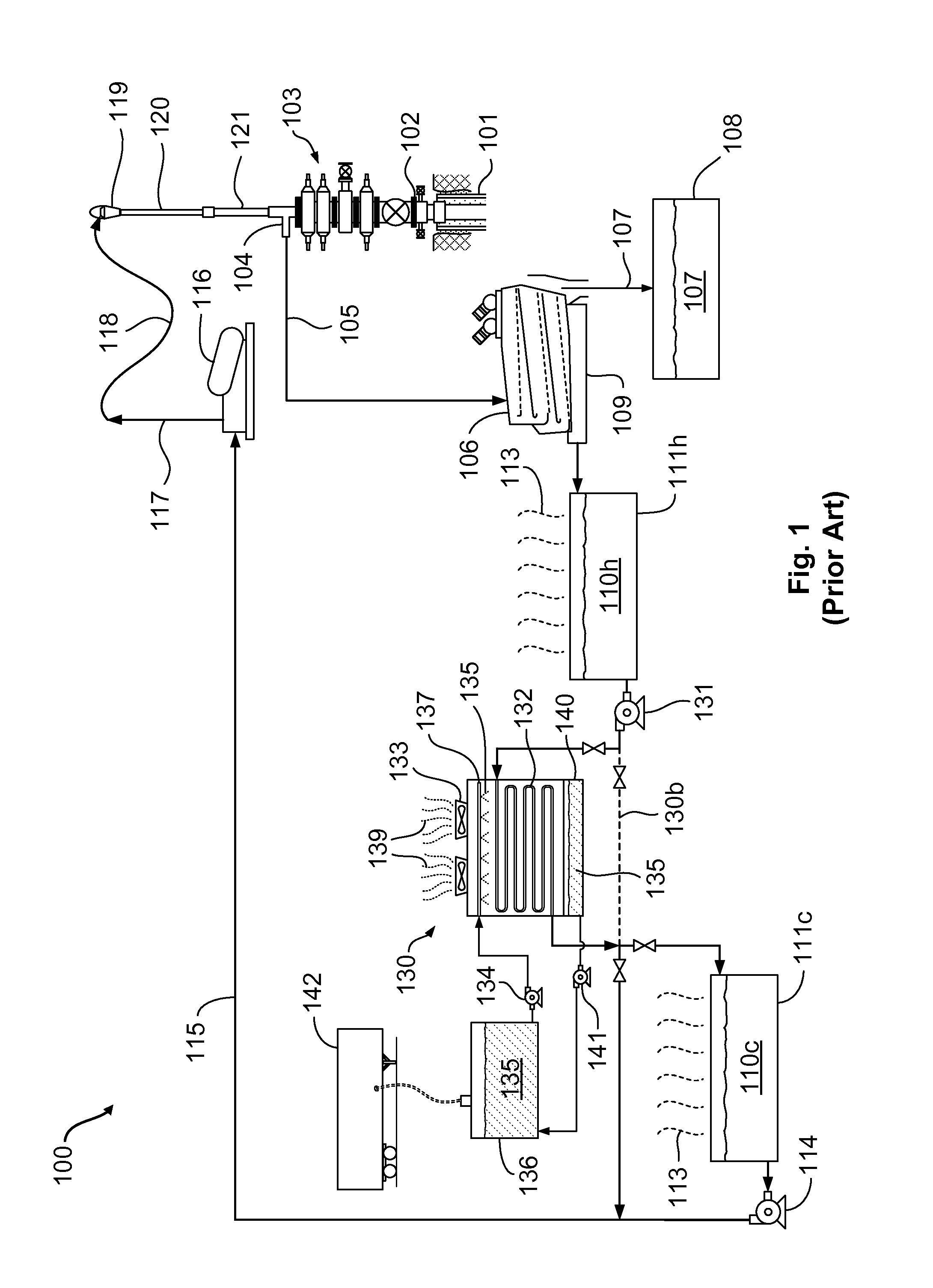
Therefore, the amount of passive cooling is typically only incremental in nature, e.g., limited to no more than approximately a 5° F. reduction in mud temperature.
Furthermore, the insulating effects attributable to the caked layer of drilling mud on the inside surfaces of the mud coil 132 can also directly reduce the overall heat transfer / cooling capabilities of the mud cooler 130.
Therefore, the replenishment of significant water losses to the surrounding environment during operation of the mud cooler 130 can have a substantial impact on the overall costs of drilling.

Method used


Image

  • Closed loop drilling mud cooling system for land-based drilling operations
  • Closed loop drilling mud cooling system for land-based drilling operations
  • Closed loop drilling mud cooling system for land-based drilling operations

Examples


Embodiment Construction

[0031]Various illustrative embodiments of the present subject matter are described below. In the interest of clarity, not all features of an actual implementation are described in this specification. It will of course be appreciated that in the development of any such actual embodiment, numerous implementation-specific decisions must be made to achieve the developers' specific goals, such as compliance with system-related and business-related constraints, which will vary from one implementation to another. Moreover, it will be appreciated that such a development effort might be complex and time-consuming, but would nevertheless be a routine undertaking for those of ordinary skill in the art having the benefit of this disclosure.

[0032]The present subject matter will now be described with reference to the attached figures. Various systems, structures and devices are schematically depicted in the drawings for purposes of explanation only and so as to not obscure the present disclosure ...


PUM


Abstract

A drilling mud cooler includes a first mud heat exchanger that is adapted to receive a flow of drilling mud, a first closed-loop cooling system that is adapted to cool a first cooling fluid that is circulated through the first mud heat exchanger so as to reduce a temperature of the flow of drilling mud from a first temperature to a second temperature, a second mud heat exchanger that is adapted to receive the flow of reduced temperature drilling mud from the first mud heat exchanger, and a second closed-loop cooling system that is adapted to cool a second cooling fluid that is circulated through the second mud heat exchanger so as to further reduce the temperature of the flow of drilling mud from the second temperature to a third temperature.

Description

BACKGROUND[0001]1. Field of the Disclosure[0002]The present subject matter is generally directed to drilling mud cooling systems, and in particular, to systems and methods that may be used for cooling drilling mud in onshore drilling applications.[0003]2. Description of the Related Art[0004]During a typical well drilling operation, such as when drilling an oil and gas well into the earth, a drilling mud circulation and recovery system is generally used to circulate drilling fluid, i.e., drilling mud, into and out of a wellbore. The drilling mud provides many functions and serves many useful purposes during the drilling operation, such as, for example, removing drill cuttings from the well, controlling formation pressures and wellbore stability during drilling, sealing permeable formations, transmitting hydraulic energy to the drilling tools and bit, and cooling, lubricating, and supporting the drill bit and drill assembly during the drilling operations.[0005]Drilling muds commonly i...

Claims


Application Information

Patent Timeline
Patent Type & Authority Applications(United States)
IPC IPC(8): E21B21/06E21B21/01E21B36/00
CPCE21B21/06E21B36/001E21B21/01
Inventor MCCRAW, GARRY
Owner NAT OILWELL VARCO LP
Why Eureka
Try Eureka