Photographing optical lens assembly, imaging device and mobile terminal

a technology of optical lenses and mobile terminals, applied in the field of compact photographing optical lens assemblies and imaging devices, can solve the problems of peripheral aberrations, inability to achieve high-order aspherical coefficients, and inability to effectively correct peripheral aberrations, so as to improve the effective range of lenses, and improve the effect of optical lens performan

Active Publication Date: 2016-01-14
LARGAN PRECISION
View PDF1 Cites 15 Cited by
  • Summary
  • Abstract
  • Description
  • Claims
  • Application Information

AI Technical Summary

Benefits of technology

[0013]When R10 / f4 satisfies the condition, it is favorable for extending the effective range of lens via the divergent beam of the whole system. In addition, the bi-aspheric design of the fourth and fifth lens elements can obtain the high order aspherical coefficient for optimal performance, so as to correct peripheral aberrations, such as, astigmatism and distortion, effectively.

Problems solved by technology

As to the conventional five-element lens structure, the object-side surface of the first lens element is convex, which cannot prevent possible damage to the lens when the lens surface is exposed to the environment, thus decreasing the imaging quality.
In addition, without having the bi-aspheric design of the fourth and fifth lens elements, it cannot obtain the high order aspherical coefficient for optimal performance, so that peripheral aberrations, such as, astigmatism and distortion, cannot be corrected effectively.

Method used


Image

  • Photographing optical lens assembly, imaging device and mobile terminal
  • Photographing optical lens assembly, imaging device and mobile terminal
  • Photographing optical lens assembly, imaging device and mobile terminal

Examples


1st embodiment

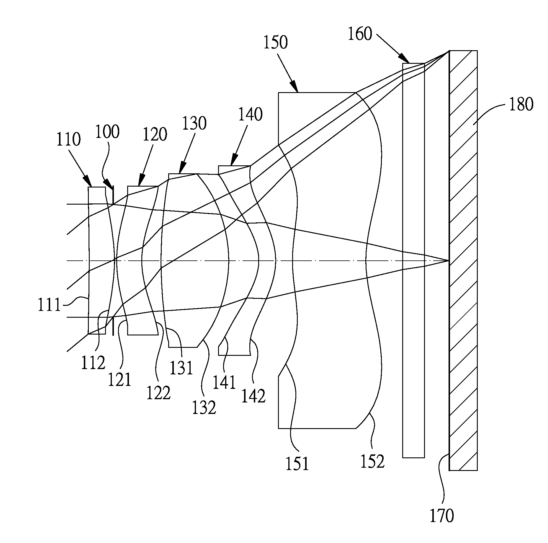
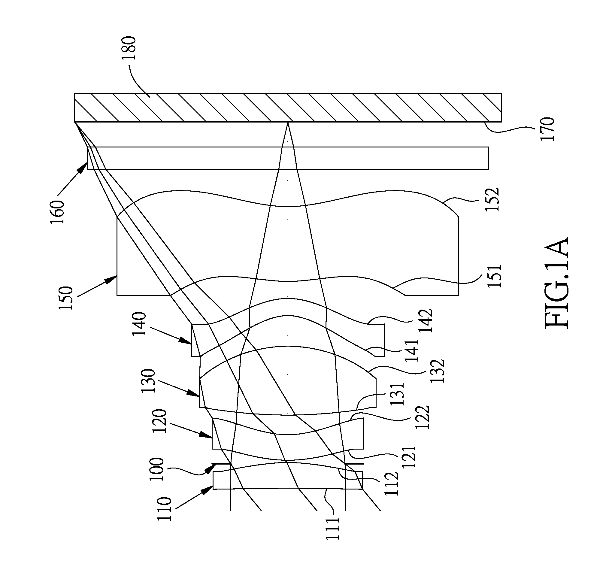
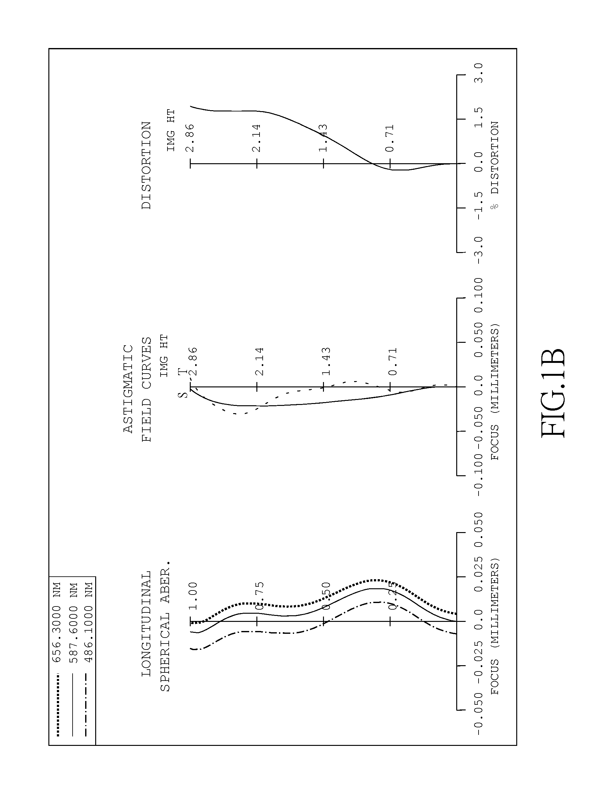
[0079]FIG. 1A is a schematic view of an imaging device according to the 1st embodiment of the present disclosure. FIG. 1B shows, in order from left to right, spherical aberration curves, astigmatic field curves and a distortion curve of the imaging unit according to the 1st embodiment.

[0080]In FIG. 1A, the imaging device includes the photographing optical lens assembly (not otherwise herein labeled) of the present disclosure and an image sensor 180. The photographing optical lens assembly comprises, in order from an object side to an image side, a first lens element 110, an aperture stop 100, a second lens element 120, a third lens element 130, a fourth lens element 140, a fifth lens element 150, an IR-cut filter 160 and an image surface 170, wherein the photographing optical lens assembly has a total of five non-cemented lens elements (110-150) with refractive power.

[0081]The first lens element 110 with positive refractive power has an aspheric object-side surface 111 being concave...

2nd embodiment

[0110]FIG. 2A is a schematic view of an imaging device according to the 2nd embodiment of the present disclosure. FIG. 2B shows, in order from left to right, spherical aberration curves, astigmatic field curves and a distortion curve of the imaging unit according to the 2nd embodiment.

[0111]In FIG. 2A, the imaging device includes the photographing optical lens assembly (not otherwise herein labeled) of the present disclosure and an image sensor 280. The photographing optical lens assembly comprises, in order from an object side to an image side, a first lens element 210, an aperture stop 200, a second lens element 220, a third lens element 230, a fourth lens element 240, a fifth lens element 250, an IR-cut filter 260 and an image surface 270, wherein the photographing optical lens assembly has a total of five non-cemented lens elements (210-250) with refractive power.

[0112]The first lens element 210 with positive refractive power has an aspheric object-side surface 211 being concave...

3rd embodiment

[0121]FIG. 3A is a schematic view of an imaging device according to the 3rd embodiment of the present disclosure. FIG. 3B shows, in order from left to right, spherical aberration curves, astigmatic field curves and a distortion curve of the imaging unit according to the 3rd embodiment.

[0122]In FIG. 3A, the imaging device includes the photographing optical lens assembly (not otherwise herein labeled) of the present disclosure and an image sensor 380. The photographing optical lens assembly comprises, in order from an object side to an image side, a first lens element 310, an aperture stop 300, a second lens element 320, a third lens element 330, a fourth lens element 340, a fifth lens element 350, an IR-cut filter 360 and an image surface 370, wherein the photographing optical lens assembly has a total of five non-cemented lens elements (310-350) with refractive power.

[0123]The first lens element 310 with positive refractive power has an aspheric object-side surface 311 being concave...


PUM


Abstract

A photographing optical lens assembly comprises, in order from an object side to an image side: a first lens element, a second lens element, a third lens element, a fourth lens element and a fifth lens element. The first lens element with refractive power has a concave object-side surface in a paraxial region. The second lens element has refractive power. The third lens element has refractive power. The fourth lens element with negative refractive power has an object-side and an image-side surfaces both being aspheric. The fifth lens element with refractive power has an aspheric object-side surface and an aspheric image-side surface being concave in a paraxial region with at least one inflection point. The photographing optical lens assembly has a total of five lens elements with refractive power.

Description

BACKGROUND[0001]1. Technical Field[0002]The present disclosure relates to a photographing optical lens assembly, imaging device and mobile terminal. More particularly, the present disclosure relates to a compact photographing optical lens assembly and imaging device applicable to a mobile terminal.[0003]2. Description of Related Art[0004]Due to the progress of science and technology, compact size has become the trend of modern electronic devices, such as, digital still camera, web camera, mobile phone camera, etc. In addition to the requirements of keeping a compact size and low cost, consumers also demand the optical lens assembly with better aberration correcting ability, high resolution and better image quality.[0005]A conventional compact photographing optical lens assembly in an electronic device typically utilizes a two-element, three-element, four-element or five-element lens structure. However, in consideration of image quality, the four-element and five-element lens structu...

Claims


Application Information

Patent Timeline
Patent Type & Authority Applications(United States)
IPC IPC(8): G02B13/00G02B9/60
CPCG02B13/0045G02B9/00G02B9/60G02B13/18H04N23/54G02B27/0025
Inventor TSAI, TSUNG-HANHUANG, HSIN-HSUAN
Owner LARGAN PRECISION
Why Eureka
Try Eureka