Laser driver and optical module including same

Inactive Publication Date: 2016-01-14
SUMITOMO ELECTRIC IND LTD
View PDF3 Cites 30 Cited by
  • Summary
  • Abstract
  • Description
  • Claims
  • Application Information

AI Technical Summary

Benefits of technology

[0009]The optical module in accordance with another aspect of the present invention comprises a laser diode (LD) configured to convert a drive current to an optical signal, the laser dr

Problems solved by technology

Such a depression often deteriorates the group delay of the optical signal em

Method used


Image

  • Laser driver and optical module including same
  • Laser driver and optical module including same
  • Laser driver and optical module including same

Examples


Embodiment Construction

[0021]In the following, an optical module in accordance with a preferred embodiment of the present invention will be explained in detail with reference to the accompanying drawings. In the explanation of the drawings, the same constituents will be referred to with the same signs while omitting their overlapping descriptions.

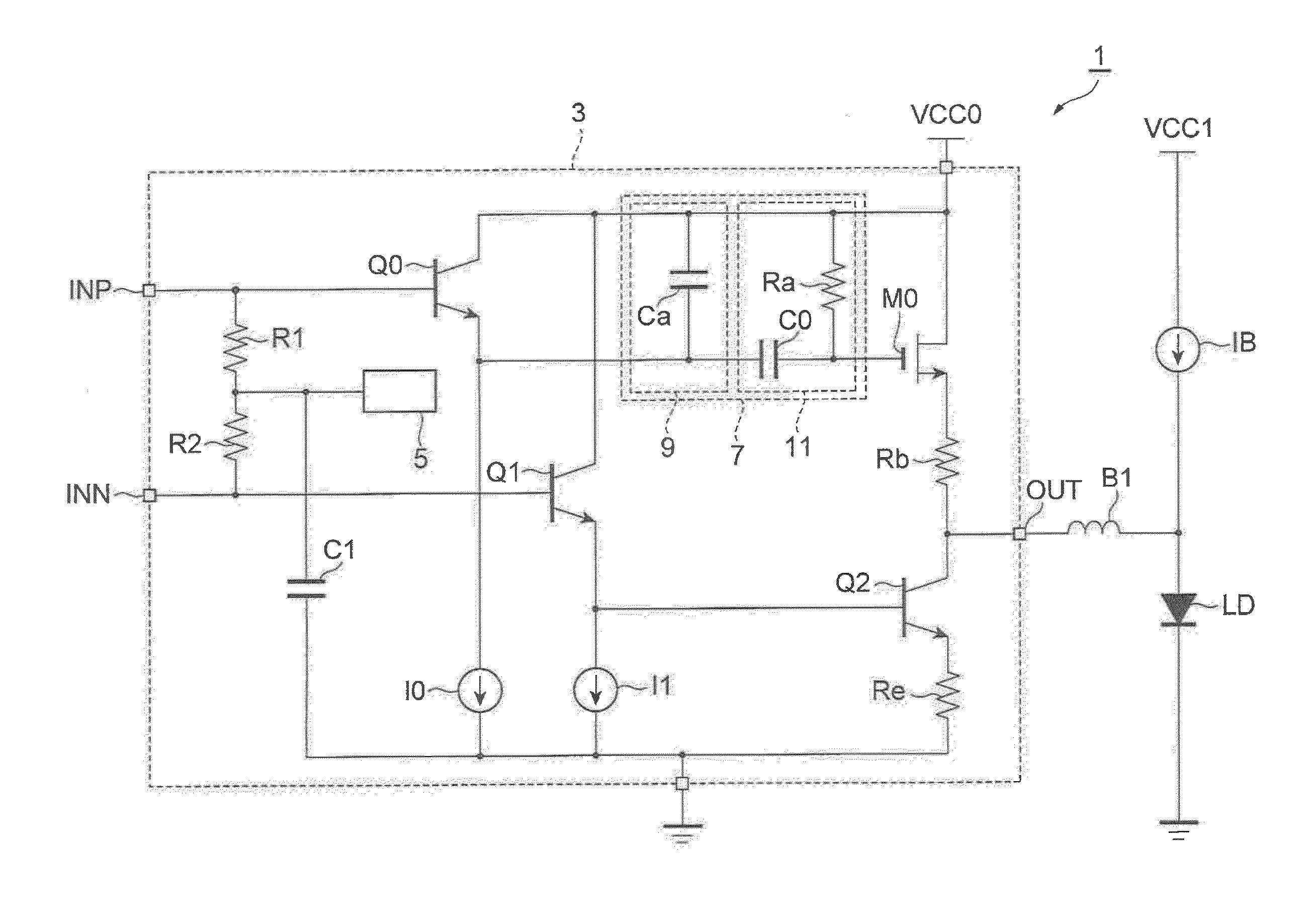
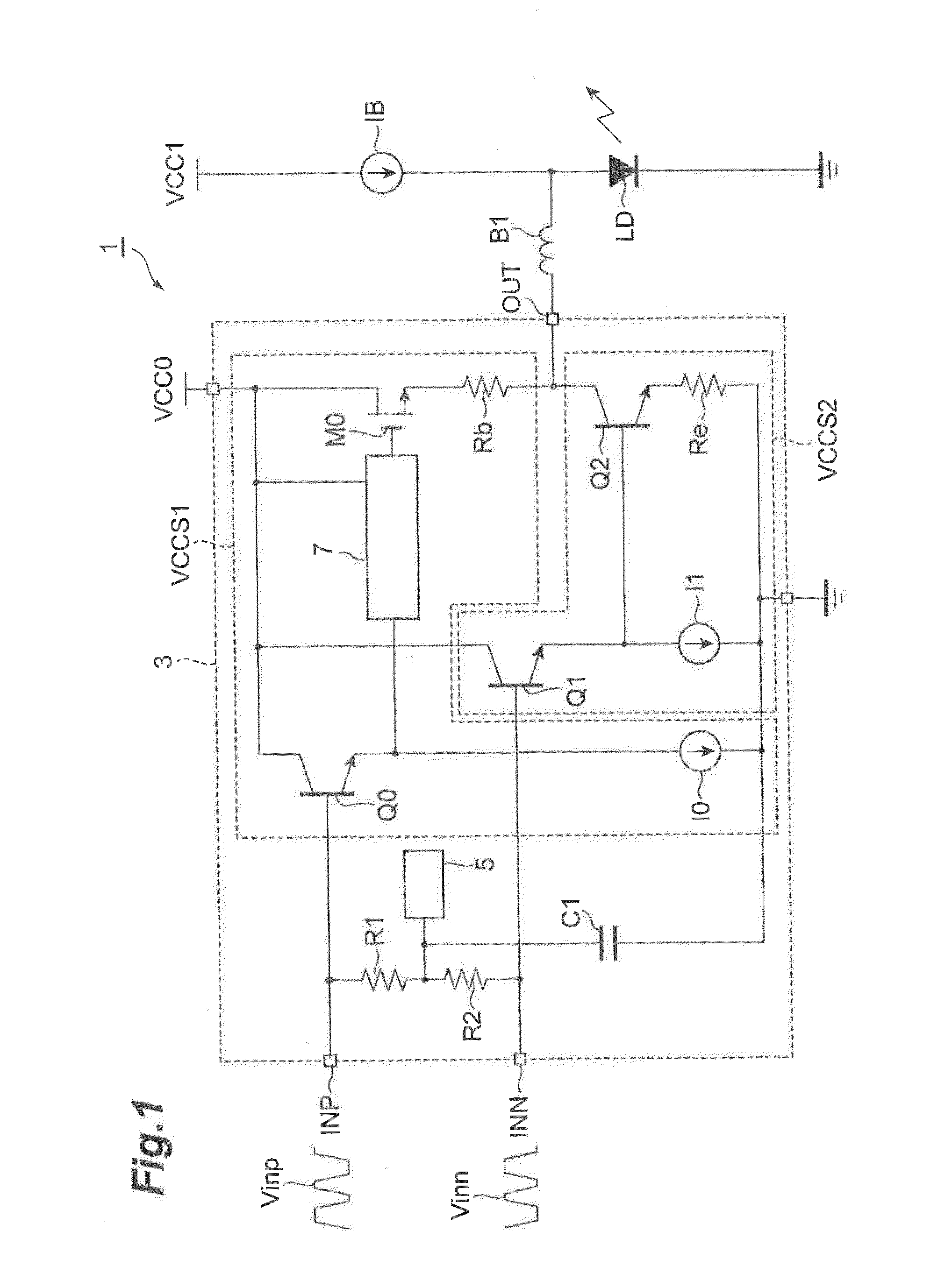
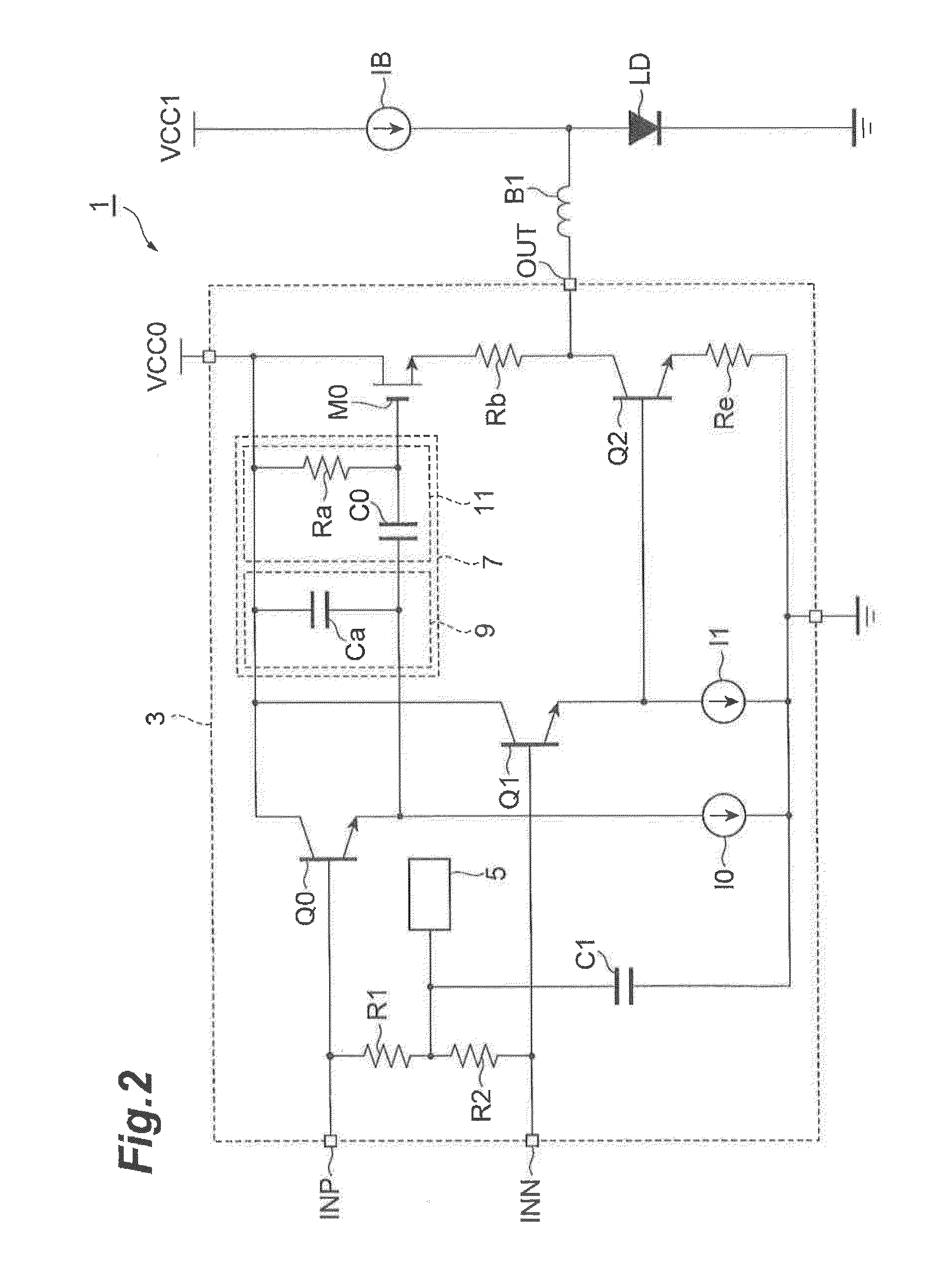
[0022]An optical module 1 in accordance with this embodiment is a TOSA (Transmitter Optical Sub-Assembly) which outputs an optical signal in response to an electric signal input from an external device. The optical module 1 includes a driver 3 for driving a laser diode (LD) by a push-pull driving-technique. FIG. 1 illustrates a schematic structure of the optical module 1.

[0023]As illustrated in this drawing, the optical module 1 mainly comprises a laser diode LD and the driver 3. An example of laser diode LD is a distributed-feedback laser diode. The driver 3 supplies a modulation current to the laser diode LD by push-pull operations described below. The laser di...


PUM


Abstract

A laser driver drives a laser diode by increasing and decreasing a drive current by a differential signal having a pair of positive phase and negative phase components and comprises an upper voltage-controlled current, source increasing the drive current responding to an increase of the positive phase component of the differential signal, a lower voltage-controlled current source for decreasing the drive current responding to an increase of the negative Phase signal of the differential signal, and an output terminal, connected to output terminals of the voltage-controlled current sources, for outputting the drive current. The voltage-controlled current source has a band-pass filter with a gain for the positive phase component set greater in a predetermined frequency region than in a frequency region other than the predetermined frequency region.

Description

BACKGROUND OF THE INVENTION[0001]1. Field of the Invention[0002]The present invention relates to a laser driver and an optical module including the same.[0003]2. Related Background Art[0004]Optical transceivers for transmitting and receiving optical signals and interconversion between the optical signals and electrical signals have been used in optical transmission systems constituting core networks and in communication lines between severs in data centers. Such an optical transceiver has a transmitter part (optical transmitter) and a receiver part (optical receiver) in general. The optical transmitter converts an electric signal into an optical signal and sends the optical signal to an optical transmission line including an optical fiber. Specifically, an optical transmitter of a “direct modulation” type incorporates therein a light-emitting element (laser diode) for generating an optical signal and a laser driver for driving the laser diode by a drive current.[0005]For the optical...

Claims


Application Information

Patent Timeline
IPC IPC(8): H01S5/022H01S5/042
CPCH01S5/0427H01S5/02248H01S5/06226
Inventor MOTO, AKIHIRO
Owner SUMITOMO ELECTRIC IND LTD
Why Eureka
Try Eureka