Endoscopic surgery device

Active Publication Date: 2016-01-21
FUJIFILM CORP
View PDF31 Cites 0 Cited by
  • Summary
  • Abstract
  • Description
  • Claims
  • Application Information

AI Technical Summary

Benefits of technology

[0019]According to the present invention, a range of an observation image acquired by an endoscope is changed with an allowance (play) with respect to a back-and-forth movement of a treatment tool. Accordingly, it is possible to prevent a size of an observation target from changing in a case where an insertion part of the treatment tool is slightly displaced in an axial direction (in a case of a back-and-forth movement of a small amplitude). As a result, a depth perception can be properly kept and a

Problems solved by technology

However, in the technique disclosed in PTL 1, it is effective in a case where the distal end of the treatment tool moves in a direction orthogonal to the visual field direction of the endoscope, but, if a zoom device is moved in interlock with a ba

Method used


Image

  • Endoscopic surgery device
  • Endoscopic surgery device
  • Endoscopic surgery device

Examples


first embodiment

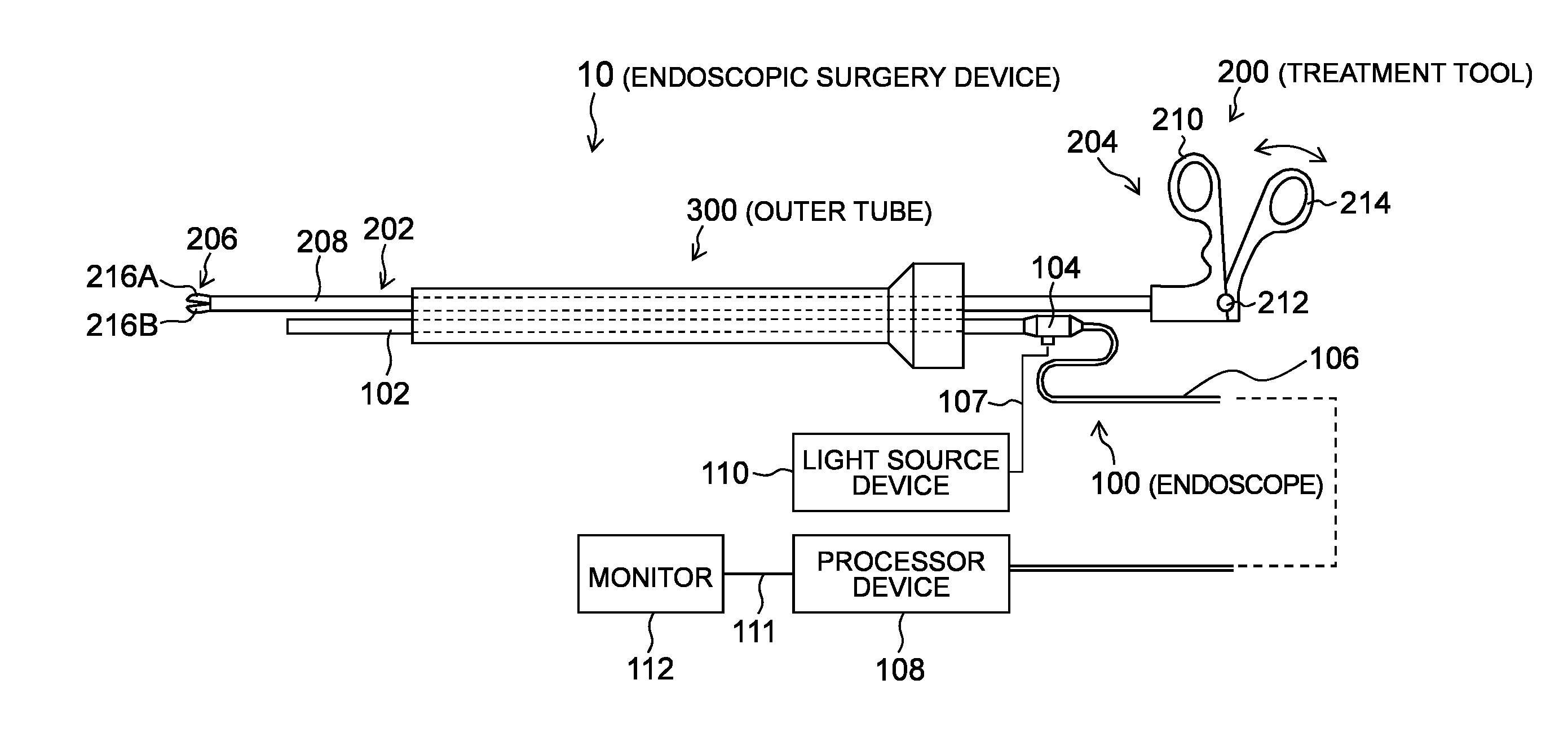
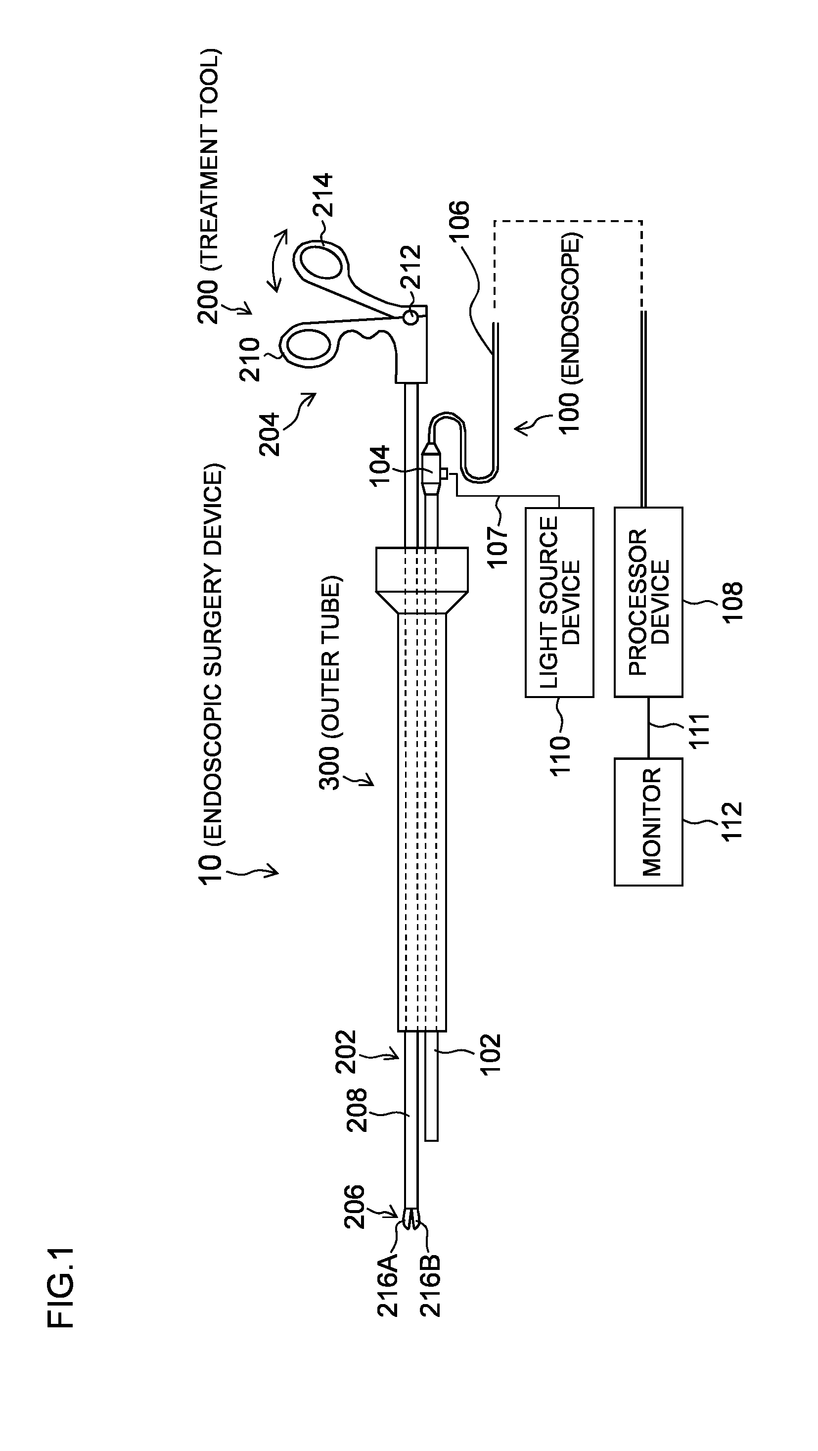
[0035]FIG. 1 is a schematic configuration diagram showing an endoscopic surgery device according to the first embodiment. As shown in FIG. 1, an endoscopic surgery device 10 of the present embodiment includes an endoscope 100 that observes the inside of a body cavity of a patient, a treatment tool 200 for inspecting or treating a diseased part in the body cavity of the patient, and an outer tube 300 that guides the endoscope 100 and the treatment tool 200 into the body cavity.

[0036]The endoscope 100 is a rigid endoscope such as a laparoscope, for example, and includes an elongated insertion part (hereinafter referred to as an “endoscope insertion part ”) 102 to be inserted into a body cavity, and an operation part 104 connected to a proximal end side of the endoscope insertion part 102. A universal cable 106 is connected to the operation part 104, and a processor device 108 is detachably connected to a top end of the universal cable 106 through a connector (not shown). In addition, ...

second embodiment

[0076]Next, a second embodiment of the present invention will be described. Hereinafter, description of a portion common to the first embodiment is omitted, and the present embodiment will be described with a focus on characteristics thereof.

[0077]FIG. 8 is a schematic configuration diagram showing a structure of a main part of an endoscopic surgery device according to the second embodiment. In FIG. 8, a component that is identical with or corresponds to that of Figures shown above is designated by the same reference numeral as that of the Figures.

[0078]In the second embodiment, as shown in FIG. 8, an observation optical system of the endoscope 100 includes a zoom lens 124 as a part of lenses thereof. The zoom lens 124 is configured to be movable in an optical axis direction with a zoom drive unit 126. The zoom lens 124 is moved in the optical axis direction to change a focal length so that magnification of a subject image imaged in an imaging element 122 is changed. As a result, ma...

third embodiment

[0084]Next, a third embodiment of the present invention will be described. Hereinafter, description of a portion common to the first and second embodiments is omitted, and the present embodiment will be described with a focus on characteristics thereof.

[0085]FIG. 9 is a functional block diagram showing a configuration of a main part of an endoscopic surgery device in accordance with the third embodiment. In FIG. 9, a component that is identical with or corresponds to that of Figures shown above is designated by the same reference numeral as that of the Figures.

[0086]In the third embodiment, as shown in FIG. 9, the processor device 108 includes an electronic zoom processing unit 134 that extracts a part of the image data created by the image data creation unit 128 to electronically perform variable magnification processing.

[0087]The control unit 130 includes an electronic zoom control unit 136 as electronic zoom control means. The electronic zoom control unit 136 changes a magnificat...


PUM


Abstract

An endoscopic surgery device that can easily acquire an image desired by a surgeon, and that has high operability. The endoscopic surgery device includes: an outer tube body; an endoscope insertion path that is provided inside the outer tube body;
a treatment tool insertion path that is provided inside the outer tube body; a position sensor that detects a movement amount of the treatment tool insertion part with respect to the outer tube body; and a control unit that has a non-sensitive area where a range of an observation image is not changed if the movement amount of the treatment tool insertion part is within a predetermined range, and a sensitive area where the range of the observation image is varied in accordance with the movement amount of the treatment tool insertion part if the movement amount of the treatment tool insertion part is not within the predetermined range.

Description

CROSS-REFERENCE TO RELATED APPLICATIONS[0001]This application is a Continuation of PCT International Application No. PCT / JP2014 / 058781 filed on Mar. 27, 2014, which claims priority under 35 U.S.C. §119(a) to Japanese Patent Application No. 2013-074017 filed on Mar. 29, 2013. Each of the above application(s) is hereby expressly incorporated by reference, in its entirety, into the present application.BACKGROUND OF THE INVENTION[0002]1. Field of the Invention[0003]The present invention relates to an endoscopic surgery device, and particularly relates to an endoscopic surgery device that can operate an endoscope and a treatment tool which are inserted in a body cavity in interlock with each other.[0004]2. Description of the Related Art[0005]Recently, endoscopic surgery using an endoscope (rigid endoscope) such as a laparoscope is widely performed because invasion to a patient is small as compared with surgery in which laparotomy and thoracotomy, and so on, are performed. For example, in...

Claims


Application Information

Patent Timeline
IPC IPC(8): A61B1/045A61B1/00A61B1/05A61B1/06
CPCA61B1/045A61B1/00154A61B1/00087A61B1/0676A61B1/05A61B1/04A61B1/00135A61B1/3132A61B17/3421A61B2017/3441A61B2017/3445A61B2017/3466A61B2090/0811A61B2034/2059A61B1/00188A61B2034/2065
Inventor IWASAKA, MASAYUKI
Owner FUJIFILM CORP
Why Eureka
Try Eureka