Implantable Micro-Fluidic Device for Monitoring of Intra-Ocular Pressure

a microfluidic device and intra-ocular pressure technology, applied in the field of microfluidic intra-ocular pressure monitoring devices, can solve the problems of inability to perform the procedure by the patient, their relatives, non-professional personnel, etc., and achieve the effect of more frequent measurements and/or home monitoring, and better patient care and treatmen

Active Publication Date: 2016-01-21
THE BOARD OF TRUSTEES OF THE LELAND STANFORD JUNIOR UNIV
View PDF5 Cites 14 Cited by
  • Summary
  • Abstract
  • Description
  • Claims
  • Application Information

AI Technical Summary

Benefits of technology

[0008]In a system and method configuration of the sensor, an imaging device, external to the area (or body) of the implant, could be used to obtain an image of the channel. An image analysis computer program could be used to quantify the intra-ocular pressure from the obtained image and the established equilibrium pressure interface. The quantified measure can then be outputted to a user. The program could be executed from the same image device, like a smart phone, or could be executed from a separate or remote computing device that receives the image from the imaging device. The embodiments of the invention are promising steps forward toward better patient care and treatment with more frequent measurements and / or home monitoring.

Problems solved by technology

Unfortunately, the accuracy of IOP measurements by GAT is affected by several factors such as corneal thickness as well as other corneal biomechanical properties.
Aside from measurement errors, another major drawback of the GAT method is the complexity of the technique.
Obviously, this procedure cannot be performed by the patients themselves, their relatives or by any other non-professional personnel, and cannot be done routinely in the supine position.
Accordingly, it is clear that since IOP is highly fluctuating, occasional measurements of IOP in the clinicians' office are not sufficient for glaucoma management and there is a need to develop technology that will enable more frequent or home monitoring of IOP in selected cases of glaucoma patients.

Method used


Image

  • Implantable Micro-Fluidic Device for Monitoring of Intra-Ocular Pressure
  • Implantable Micro-Fluidic Device for Monitoring of Intra-Ocular Pressure
  • Implantable Micro-Fluidic Device for Monitoring of Intra-Ocular Pressure

Examples


first embodiment

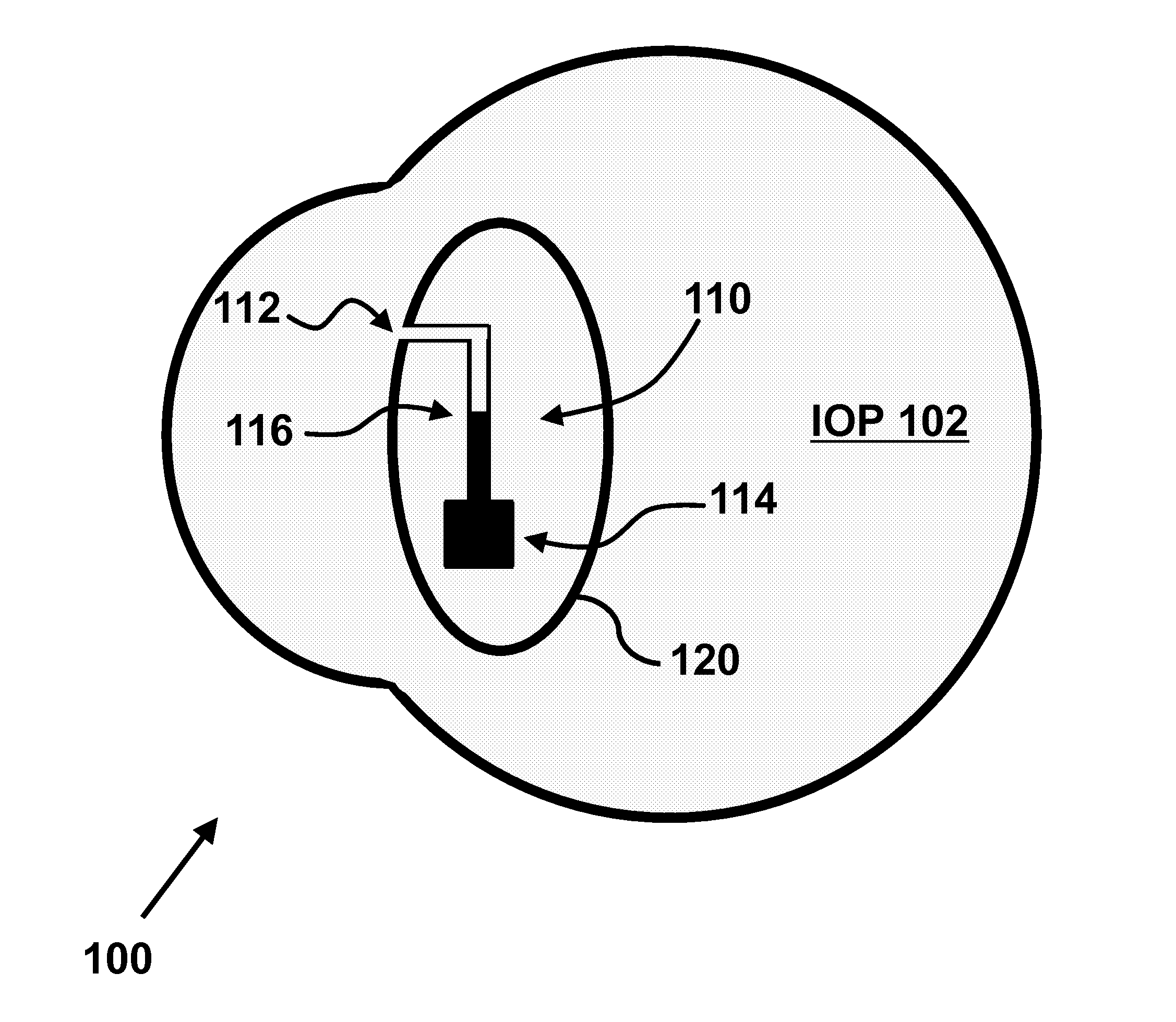
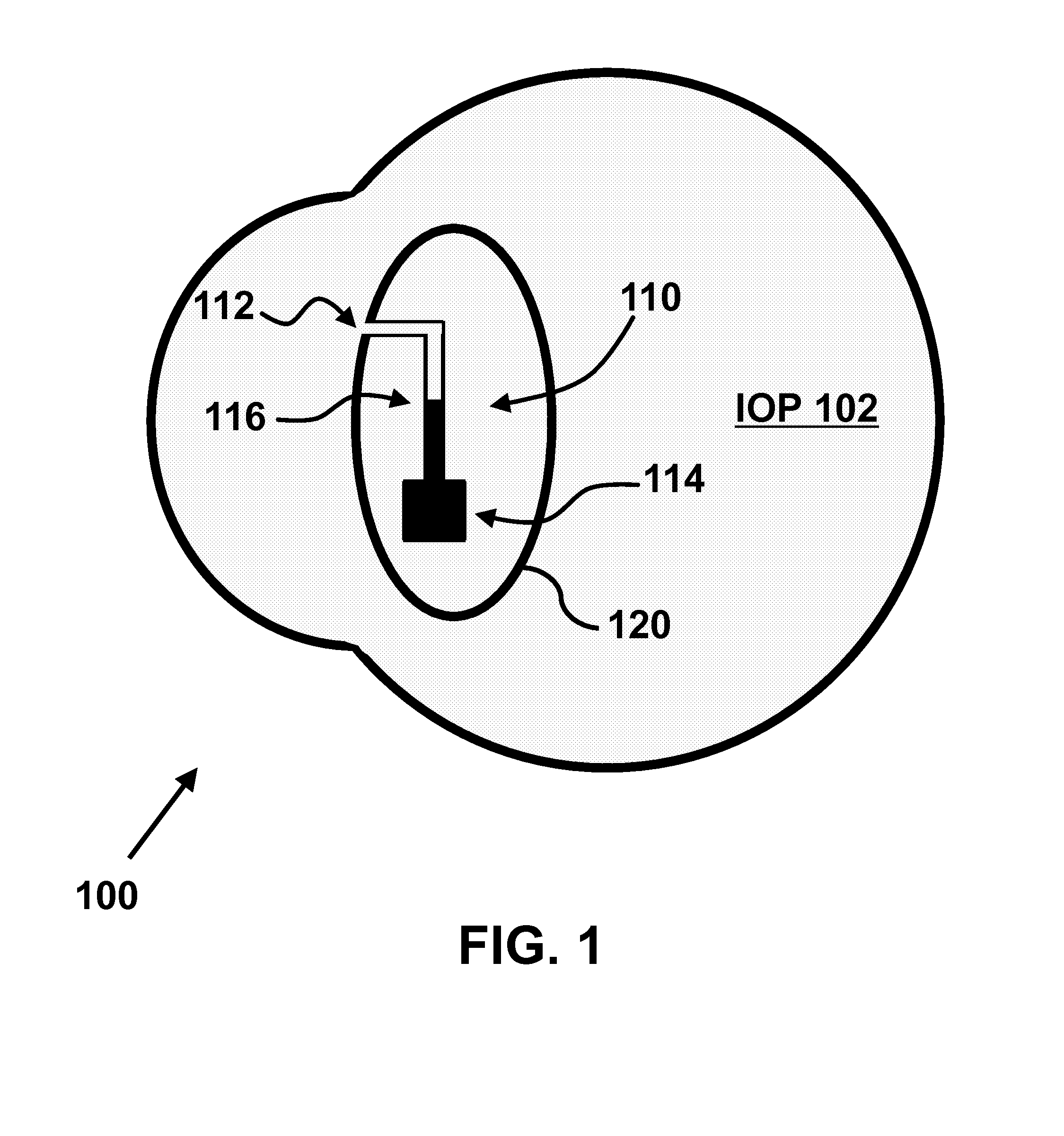
[0018]In a first embodiment, the IOP sensor has a microfluidic channel 112 open to an aqueous intraocular liquid on one end and connected to a gas chamber or reservoir 114 on the other end (gas is indicated as black for illustration purposes). Capillary forces between the inner wall of the channel and the intraocular liquid and a positive intraocular pressure hold the liquid within at least part of the channel. Increased intraocular pressure 102 would drive the liquid further into the micro-channel 112, compressing the gas inside the reservoir until gas pressure is in equilibrium with liquid pressure as indicated by (gas-fluid) interface 116. Increased intraocular pressure causes the (gas-fluid) interface 116 to shift toward the channel's dead end (the gas reservoir), while decreasing the IOP causes a shift toward the channel opening.

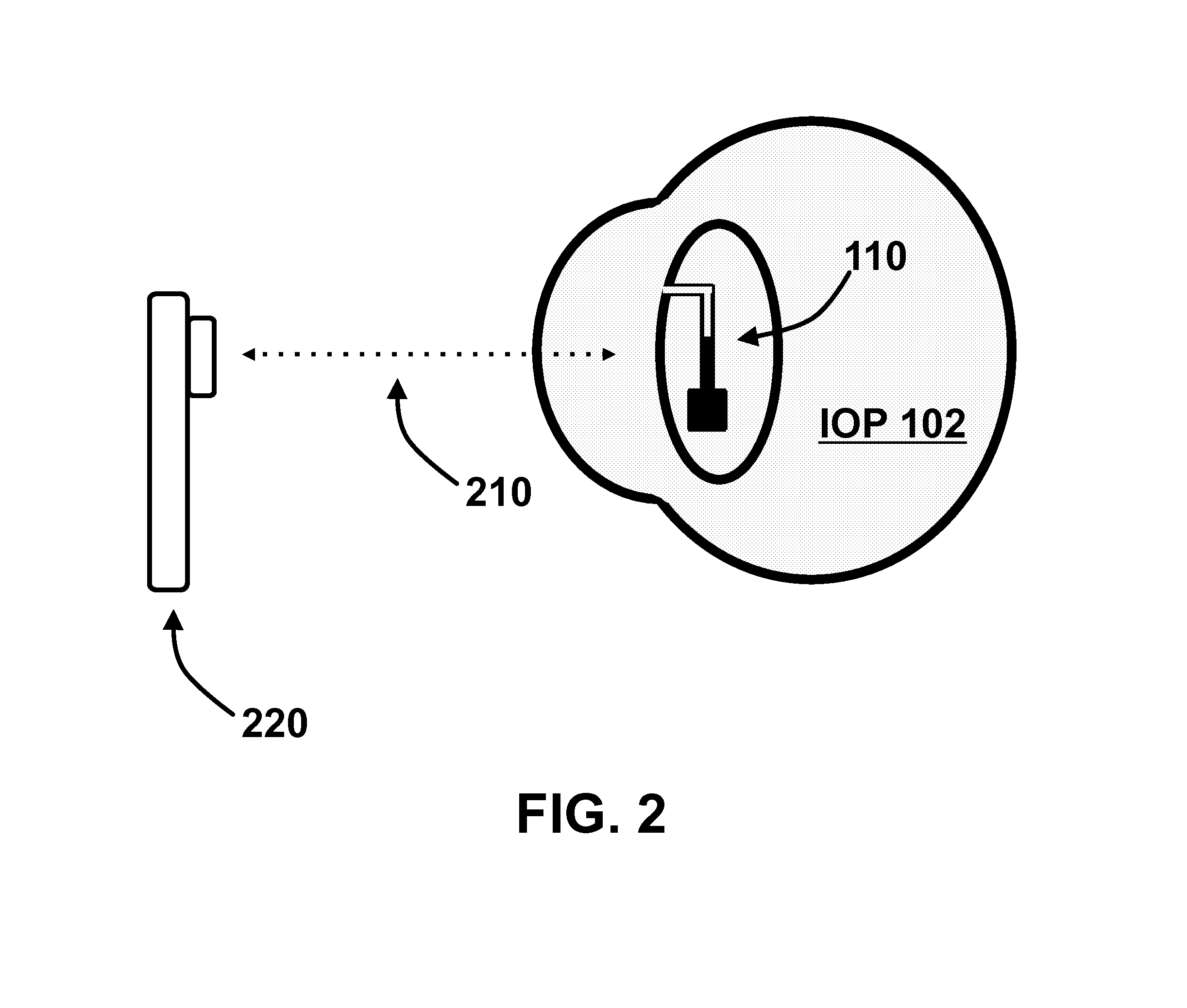
[0019]Intra-Ocular Pressure readout can be accomplished optically by passing light 210 with wavelength in the range of transparency to the ocular optic...

second embodiment

[0024]The intraocular pressure could be transmitted to the intra-channel fluid through one or more openings in the channel or through a thin flexible membrane with a surface area in the range of 100 μm square to 100 mm square as described with respect to the sensor.

[0025]In a second embodiment shown in FIG. 9, the IOP sensor 910 has a flexible thin membrane 920 covering a fluid filled reservoir 930, which is connected to a small cross section channel 940 with a dead end. Changes in the IOP cause shifts of fluid volume from the reservoir to the channels and therefore, a movement of the liquid-air (or other gasses) interface 950. Adding color to the fluid in the example could further enhance the visibility of the fluid column (not shown). Alternatively, two fluids with two different colors can be used.

[0026]A temperature sensor can be incorporated in the sensor and can be used for pressure correction. Temperature sensor could be incorporated near the IOP sensor or in a separate device...


PUM


Abstract

Glaucoma is the second most common cause of blindness in the global world. It is a multifactorial disease with several risk factors, of which intraocular pressure (IOP) is the most important. IOP measurements are used for glaucoma diagnosis and patient monitoring. IOP has wide diurnal fluctuation, and is dependent on body posture, so the occasional measurements done by the eye care expert in clinic can be misleading. We provide an implantable sensor, based on microfluidic principles, which in one example has 1 mmHg limit of detection, high sensitivity and excellent reproducibility. This sensor has an optical interface, which enables IOP to be read with, for example, a cell phone camera. The design, fabrication, along with the option of self-monitoring are promising steps toward better patient care and treatment for this devastating disease.

Description

FIELD OF THE INVENTION[0001]This invention relates to micro-fluidic intra-ocular pressure monitoring devices, systems and methods. In particular, the invention relates to passive intra-ocular pressure monitoring implants with an external readout mechanism.BACKGROUND OF THE INVENTION[0002]Glaucoma affects more than 65 million people worldwide and is expected to affect about 80 million people in 2020. It is second only to cataracts in frequency of causing blindness in the global world. Glaucoma is characterized by a progressive loss of retinal ganglion cells, a characteristic optic neuropathy and patterns of visual field loss in the more advanced stages. The pathogenesis of glaucoma is multifactorial with several recognized risk factors of which increased intraocular pressure (IOP) is the most important one.[0003]Normal IOP ranges between 10 to 21 mmHg with an average of 15.3 mmHg. Lowering IOP by medications or surgery is the only therapeutic modality currently available. Therefore, ...

Claims


Application Information

Patent Timeline
Patent Type & Authority Applications(United States)
IPC IPC(8): A61B5/00A61B3/16
CPCA61B3/16A61B2576/00A61B5/6821A61B19/5212A61B90/361
Inventor MANDEL, YOSEFARACI, ISMAIL EQUAKE, STEPHEN R.
Owner THE BOARD OF TRUSTEES OF THE LELAND STANFORD JUNIOR UNIV
Why Eureka
Try Eureka