Method and apparatus for performing laser curved filamentation within transparent materials

a technology of transparent materials and lasers, applied in glass rolling apparatus, glass tempering apparatus, manufacturing tools, etc., can solve the problems of angled lenses losing a lot of laser power, spatial light modulators generally damage, etc., to facilitate the formation of c-shaped curved filament arrays, improve bending strength, and avoid chips or cracks

Active Publication Date: 2016-01-21
ROFIN SINAR TECH
View PDF0 Cites 48 Cited by
  • Summary
  • Abstract
  • Description
  • Claims
  • Application Information

AI Technical Summary

Benefits of technology

[0017]C-cut facets enhance bending strength and avoid formation of chips or cracks. The prior art uses additional manufacturing steps such as mechanical grinding to achieve C-cut facets.
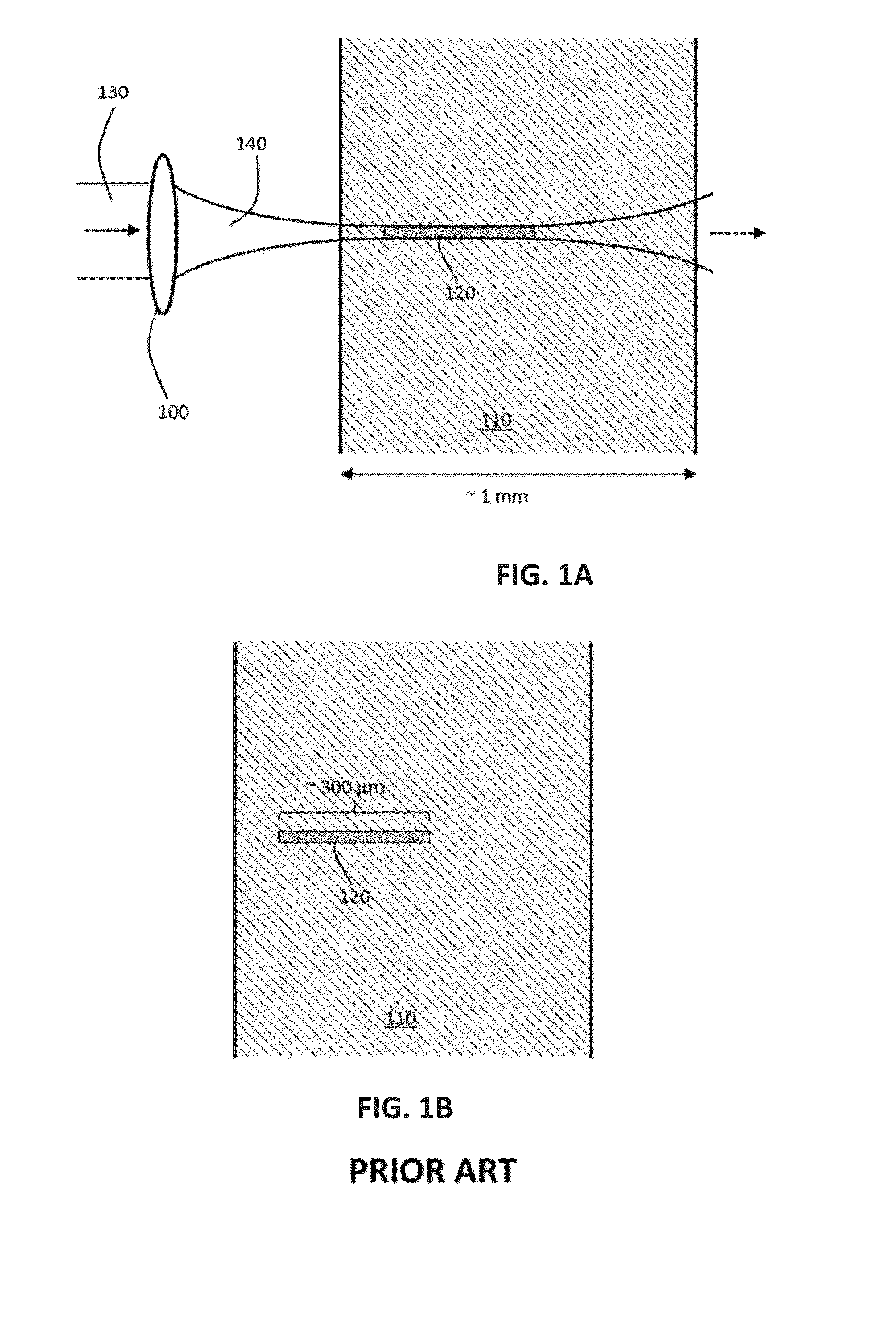
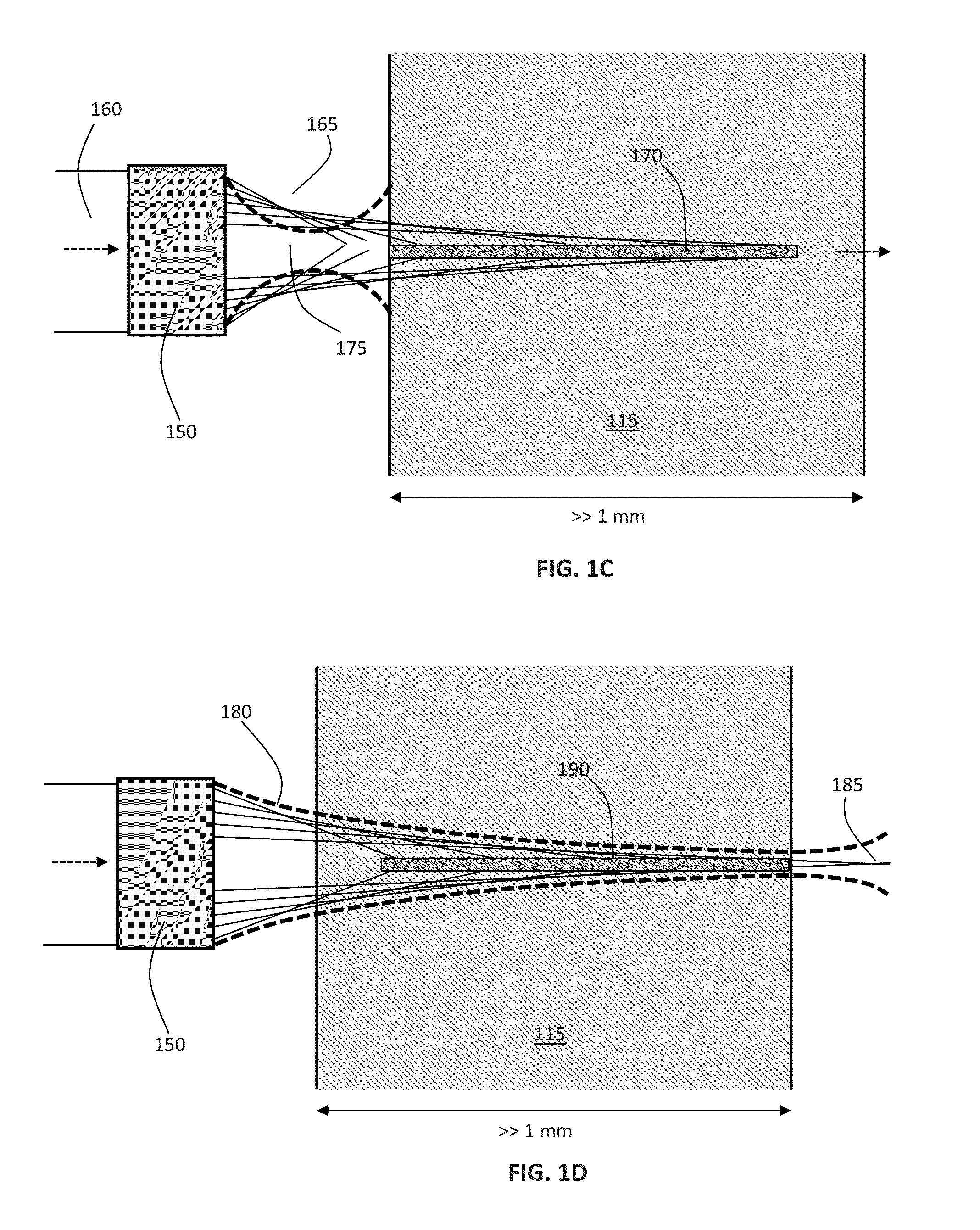
[0018]Filaments formed according to this method may exhibit lengths exceeding up to 10 mm with a 1:1 correspondence in the length of the modified zone (in that the filament is the agent of modification, so the modified zone tracks 1:1 with the extent of the filament) and a taper-free profile when viewed with the long axis in cross

Problems solved by technology

A spatial light modulator generally damage if an intense lase

Method used


Image

  • Method and apparatus for performing laser curved filamentation within transparent materials
  • Method and apparatus for performing laser curved filamentation within transparent materials
  • Method and apparatus for performing laser curved filamentation within transparent materials

Examples


Embodiment Construction

[0059]Various embodiments and aspects of the disclosure will be described with reference to details discussed below. The following description and drawings are illustrative of the disclosure and are not to be construed as limiting the disclosure. Numerous specific details are described to provide a thorough understanding of various embodiments of the present disclosure. However, in certain instances, well-known or conventional details are not described in order to provide a concise discussion of embodiments of the present disclosure.

[0060]As used herein, the terms, “comprises” and “comprising” are to be construed as being inclusive and open ended, and not exclusive. Specifically, when used in the specification and claims, the terms, “comprises” and “comprising” and variations thereof mean the specified features, steps or components are included. These terms are not to be interpreted to exclude the presence of other features, steps or components.

[0061]As used herein, the term “exempl...


PUM

PropertyMeasurementUnit
Lengthaaaaaaaaaa
Lengthaaaaaaaaaa
Pressureaaaaaaaaaa

Abstract

Systems and methods are described for forming continuous curved laser filaments in transparent materials. The filaments are preferably curved and C-shaped. Filaments may employ other curved profiles (shapes). A burst of ultrafast laser pulses is focused such that a beam waist is formed external to the material being processed without forming an external plasma channel, while a sufficient energy density is formed within an extended region within the material to support the formation of a continuous filament, without causing optical breakdown within the material. Filaments formed according to this method may exhibit lengths in the range of 100 μm-10 mm. An aberrated optical focusing element is employed to produce an external beam waist while producing distributed focusing of the incident beam within the material. Optical monitoring of the filaments may be employed to provide feedback to facilitate active control of the process.

Description

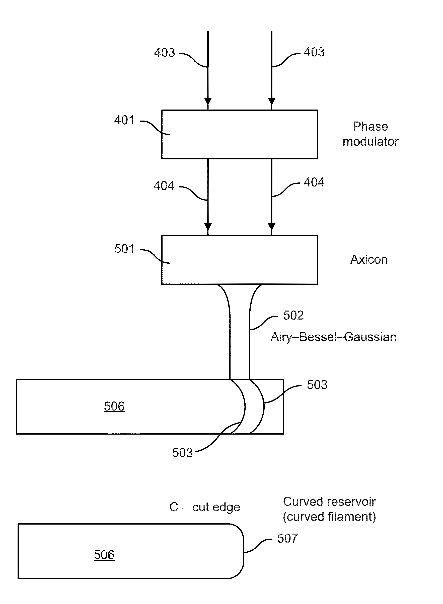
[0001]This is a continuation in part of co-pending U.S. patent application Ser. No. 14 / 336,819 filed Jul. 21, 2014. U.S. patent application Ser. No. 14 / 336,819 filed Jul. 21, 2014 is incorporated herein in its entirety by reference hereto.FIELD OF THE INVENTION[0002]The invention is in the field of laser filamentation within transparent materials.BACKGROUND OF THE INVENTION[0003]The present disclosure is related to systems and methods for the laser processing of materials. More particularly, the present disclosure is related to systems and methods for the singulation and / or cleaving of wafers, substrates, and plates that might contain passive or active electronic or electrical devices created thereon.[0004]In the process, the filament is forced to curve in a profile to form a facet with a C-shaped in cross-section profile. There is huge demand in the brittle material industry to singulate samples with a C-shaped in cross-section facet profile. The C-shaped in cross-section facet pro...

Claims


Application Information

Patent Timeline
IPC IPC(8): B23K26/0622B23K26/00C03B33/033C03B33/04C03B33/09
CPCB23K26/0622C03B33/04C03B33/033B23K2203/56B23K26/0006B23K26/0057B23K2203/54C03B33/091B23K26/53B23K26/0624B23K26/0648B23K26/082B23K26/38B23K2103/16B23K2103/166B23K2103/42B23K2103/50B23K2103/52B23K2103/54B23K2103/56C03B33/0222C03B33/07
Inventor HOSSEINI, S., ABBAS
Owner ROFIN SINAR TECH
Why Eureka
Try Eureka