Booster, resistance force applying apparatus, and stroke simulator

Inactive Publication Date: 2016-01-21
HITACHI AUTOMOTIVE SYST LTD
View PDF5 Cites 13 Cited by
  • Summary
  • Abstract
  • Description
  • Claims
  • Application Information

AI Technical Summary

Benefits of technology

[0008]According to the present invention, the operator can oper

Problems solved by technology

However, the above-described technique disclosed in Japanese Patent Application Public Disclosure No. 2013-10470 involves such a problem that the reaction force and the friction force are acquired with the aid of the elastic fr

Method used


Image

  • Booster, resistance force applying apparatus, and stroke simulator
  • Booster, resistance force applying apparatus, and stroke simulator
  • Booster, resistance force applying apparatus, and stroke simulator

Examples


first embodiment

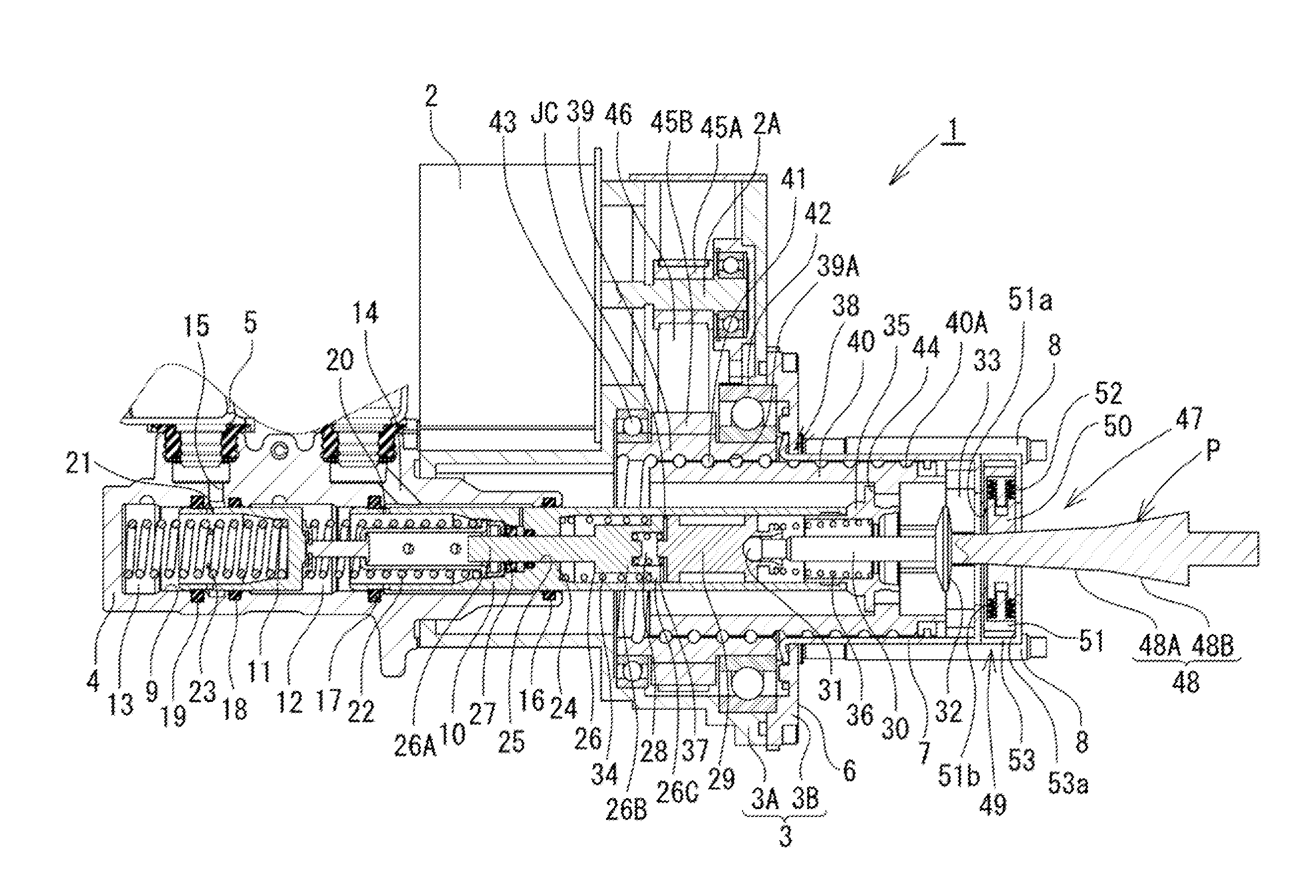
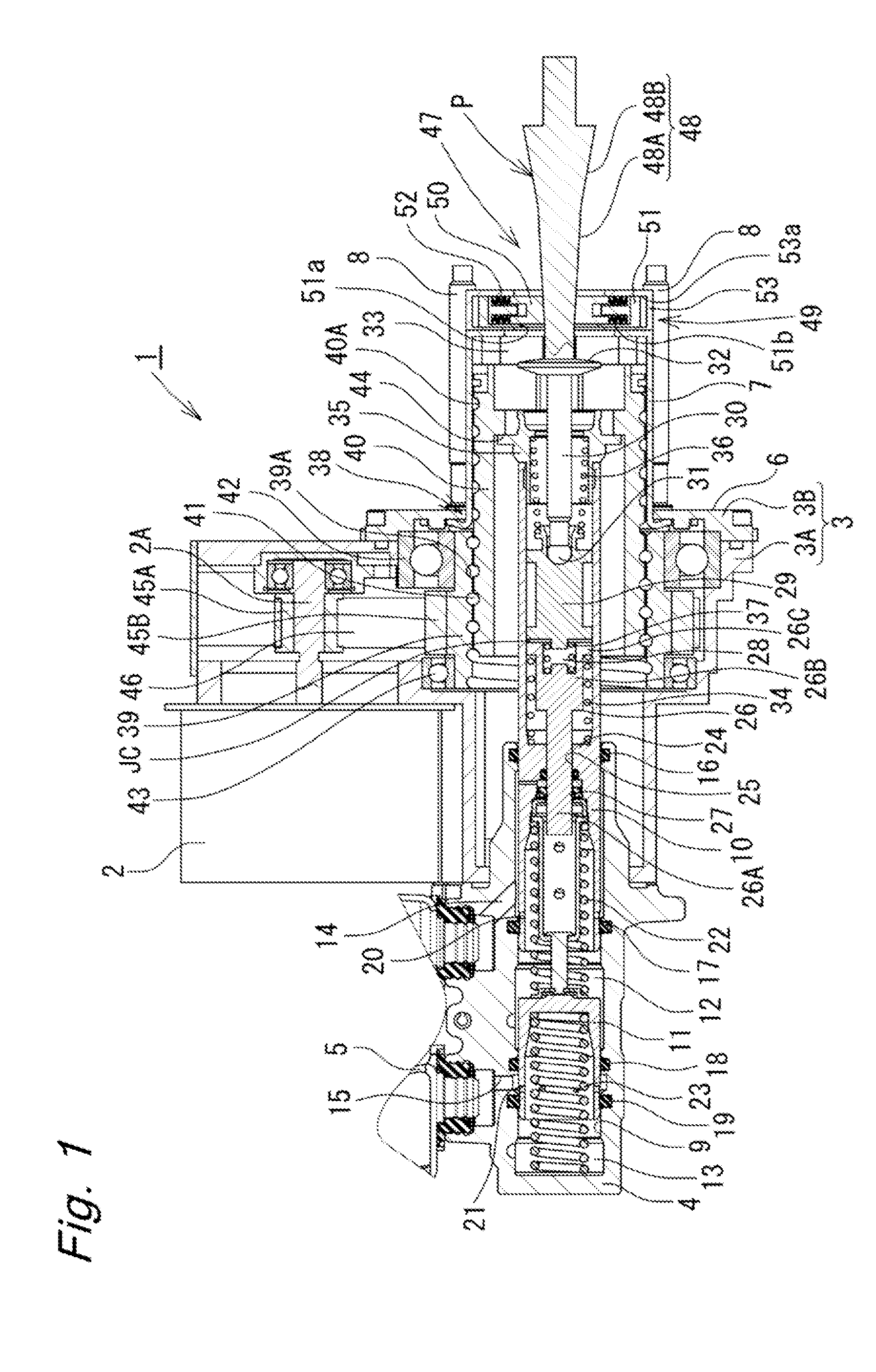
[0019]In the following description, embodiments of the present invention will be described in detail with reference to the drawings. An electric booster according to the present invention will be described with reference to FIGS. 1 to 4.

[0020]As illustrated in FIG. 1, the electric booster 1 according to the present embodiment is a booster that operates with use of an electric motor 2, which is an electric actuator, as a driving source thereof. The electric booster 1 has a structure including a housing 3 and a tandem-type master cylinder 4 coupled to one axial side (a front side, a left side in FIG. 1) of the housing 3. A reservoir 5 (only a part thereof illustrated), which supplies brake fluid to the master cylinder 4, is mounted on a top of the master cylinder 4. The housing 3 is formed by coupling a rear cover 3B to an opposite end side of a generally cylindrical stepped front housing 3A.

[0021]A fiat mounting seat surface 6 is formed at the rear cover 3B of the housing 3. A cylind...

second embodiment

[0063]Next, the present invention will be described with reference to FIGS. 7 and 8. The present embodiment is an embodiment in which the present invention is applied to a stroke simulator that exerts a reaction force to a brake pedal while being mounted in a so-called brake-by-wire system that generates a braking force in response to an electric signal based on a stroke of the brake pedal without the brake pedal and a frictional brake directly mechanically connected to each other via a hydraulic circuit and the like.

[0064]As illustrated in FIG. 7, a stroke simulator 70 according to the present embodiment includes a generally bottomed cylindrical housing 71, a slider 72 that is axially movably guided, in the housing 71, an input rod 73 connecting the slider 72 and a brake pedal (not illustrated) to each other and serving as an input member inserted in the housing 71, and a reaction force spring 74 that is a compression coil spring disposed between a bottom of the housing 71 and the ...

third embodiment

[0072]Next, the present embodiment will be described with reference to FIGS. 9 and 10. The present embodiment is a resistance force applying mechanism that is mounted at a shaft supporting a brake pedal, and applies a resistance force against a stroke of the brake pedal.

[0073]As illustrated in FIG. 9, a resistance force applying mechanism 83 is mounted at a rotational shaft 82 of a brake pedal 81 rotatably supported by a brake bracket 80. An input rod 84, which transmits a force of operating the brake pedal 81 to a brake system (not illustrated), is coupled to the brake pedal 81.

[0074]As illustrated in FIG. 10A, the resistance force applying mechanism includes a generally bottomed cylindrical housing 85 fixed to the brake pedal bracket 80, a rotational cam member 86 that is a rotational member disposed in the housing 85, a linearly moving cam member 87 that is a sliding member opposite from the rotational cam member 86, and a spring member 88 that is a compression coil spring dispos...


PUM


Abstract

The present invention controls an electric motor according to a stroke that an input rod performs in response to an operation performed on a brake pedal, and thrusts a primary piston, thereby generating a brake hydraulic pressure in a master cylinder. The brake hydraulic pressure is fed back to the input rod via an input piston and an input plunger. The present invention applies a sliding resistance against the stroke of the input rod by pressing a frictional member of a resistance force applying mechanism against a tapering sliding portion of the input rod with the aid of a spring force of a spring member. A taper angle of the sliding portion allows the sliding resistance to change at a varying ratio according to a position of the input rod, which can lead to stable application of a desired sliding resistance.

Description

TECHNICAL FIELD[0001]The present invention relates to a booster, a resistance force applying apparatus, and a stroke simulator mounted in a brake apparatus of a vehicle such as an automobile.BACKGROUND ART[0002]For example, Japanese Patent Application Public Disclosure No. 2013-10470 discloses a technique for improving a feeling that an operator has when operating a brake pedal, by applying a reaction force and a friction force against a stroke of the brake pedal with use of an elastic frictional member such as a rubber in such a manner that a difference is made in the reaction force (a hysteresis) between when the operator presses the brake pedal and when the operator releases the brake pedal.SUMMARY OF INVENTION[0003]However, the above-described technique disclosed in Japanese Patent Application Public Disclosure No. 2013-10470 involves such a problem that the reaction force and the friction force are acquired with the aid of the elastic frictional member such as the robber, and t...

Claims


Application Information

Patent Timeline
IPC IPC(8): B60T8/40B60T7/04
CPCB60T8/4077B60T8/4086B60T7/042B60T7/04B60T13/745
Inventor ODAIRA, ATSUSHIUSUI, TAKUYA
Owner HITACHI AUTOMOTIVE SYST LTD
Why Eureka
Try Eureka