Mask inspection apparatus and mask inspection method

a mask inspection and mask technology, applied in the field of mask inspection apparatus and mask inspection method, can solve the problems of large degradation of production yield, inability to generate design data or reference image data in real time, and difficulty in matching the scan speed of acquiring optical images with the scan speed of reference images, so as to achieve easy storage of large capacity data, increase the capacity of storage, and high speed

Active Publication Date: 2016-01-21
NUFLARE TECH INC
View PDF12 Cites 20 Cited by
  • Summary
  • Abstract
  • Description
  • Claims
  • Application Information

AI Technical Summary

Benefits of technology

[0013]In order to perform the die-to-database comparison inspection in real time, it is necessary to process a huge capacity of data at a high speed, and it is difficult to match a reference image generation with a scan speed for acquiring an optical image. However, since an increase in the capacity of the storage is progressing, storing large capacity data has become easy.
[0014]As described above, instead of a method of comparing a reference image with an optical image in real time, there is disclosed an entire image acquisition and inspection method of acquiring an optical image of an entire inspection region and comparing the acquired...

Problems solved by technology

At this point, a defect of the mask pattern can be cited as a large factor of degradation in the production yield.
Thus, it is difficult to generate design data or reference image data in real time.
That is, in order to perform the die-to-database comparison inspection, it is necessary to process a huge amount of data at a high speed, and it is the...

Method used


Image

  • Mask inspection apparatus and mask inspection method
  • Mask inspection apparatus and mask inspection method
  • Mask inspection apparatus and mask inspection method

Examples


Embodiment Construction

[0026]The embodiments will now be described with reference to the accompanying drawings, wherein the same reference numerals designate corresponding or identical elements throughout the various drawings.

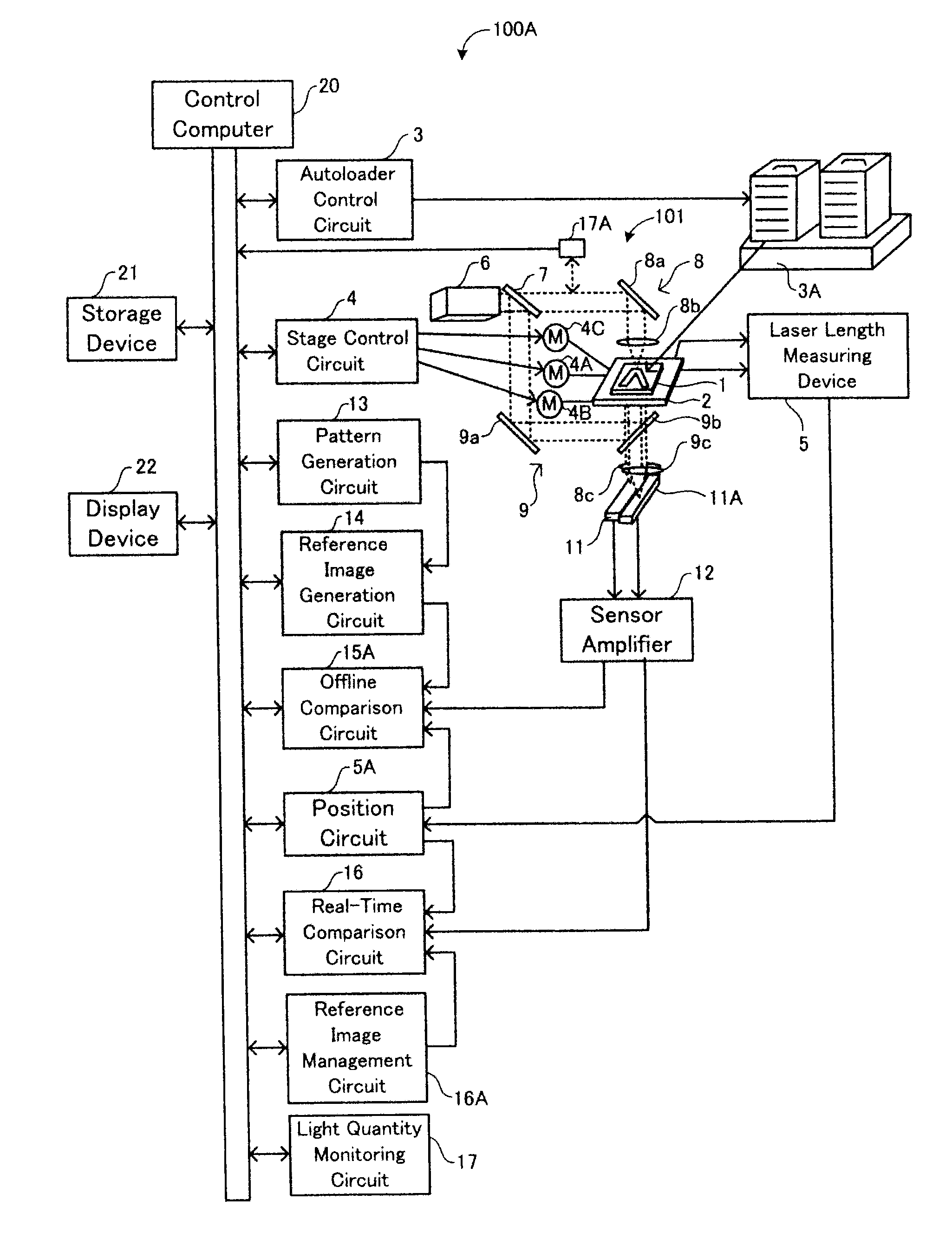
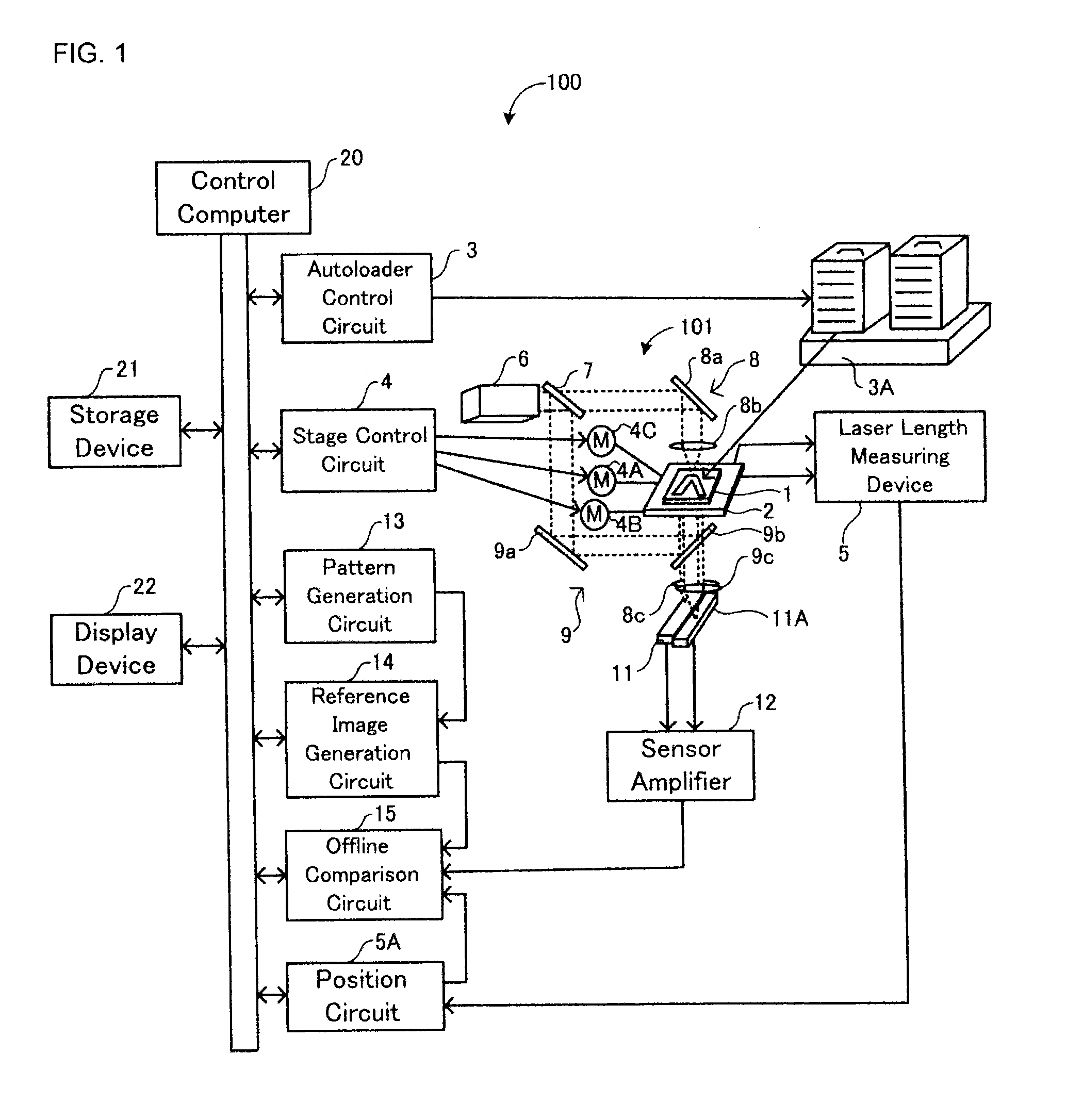
[0027]FIG. 1 is a schematic diagram illustrating a configuration of a mask inspection apparatus 100 as one embodiment of a mask inspection apparatus according to the present invention.

[0028]In the mask inspection apparatus 100, a light is irradiated on the mask 1 to inspect defects of patterns formed in the mask 1 as shown in FIG. 1. In FIG. 1, a configuration unit necessary in the present embodiment is illustrated. However, another well-known configuration unit necessary for an inspection may also be included. As used herein, a “unit” or “circuit” can be configured by a program operating on a computer. Alternatively, the “unit” or “circuit” may be constructed by, not only a software program, but also a combination of software, hardware, or firmware. In the case that the “unit” or “c...


PUM


Abstract

In a mask inspection apparatus, a defect detection unit includes a first memory region, a second memory region, an inspection condition reconfiguring unit, and a comparison unit. The inspection condition reconfiguring unit obtains a difference between gray scales of an optical image stored in the second memory region and a reference image stored in the first memory region. The existence of the defect is determined in the case where the difference is larger than a first threshold value. Further in the case where the number of defects is larger than a second threshold value, an inspection condition is re-estimated and configured and the reference image is regenerated. A comparison unit compares the stored reference image with the stored optical image in the case where the inspection condition is not reconfigured, and compares the regenerated reference image with the stored optical image in the case where the inspection condition is reconfigured.

Description

CROSS-REFERENCE TO THE RELATED APPLICATION[0001]The entire disclosure of the Japanese Patent Application No. 2014-145114, filed on Jul. 15, 2014 including specification, claims, drawings, and summary, on which the Convention priority of the present application is based, are incorporated herein in its entirety.FIELD OF THE INVENTION[0002]The present invention relates to a mask inspection apparatus and a mask inspection method.BACKGROUND[0003]Recently, higher mounting densities and larger capacities of large-scale integrated (LSI: Large Scale Integration) circuits are further reducing the circuit line widths needed for semiconductor devices. By using an original image pattern (that is, a mask or a reticle, hereinafter collectively referred to as a mask) in which a circuit pattern is formed, the pattern is exposed and transferred onto a wafer by a reduction projection exposure apparatus, called a stepper or a scanner, to form a circuit on the wafer, thereby producing a semiconductor el...

Claims


Application Information

Patent Timeline
IPC IPC(8): G06T7/00H04N5/225H04N5/232
CPCG06T7/0008H04N5/2256G06T2207/30148G06T2207/10004H04N5/23229G06T7/001G03F1/84G06T2207/20224
Inventor INOUE, TAKAFUMI
Owner NUFLARE TECH INC
Why Eureka
Try Eureka