
Method and apparatus for making amorphous metal transformer cores

a technology of transformer cores and metal strips, applied in the field of transformer cores, can solve the problems of amorphous metal strips, heat generation, and transformer losses, and achieve the effects of reducing the number of transformer cores, and improving the quality of transformer cores

Active Publication Date: 2016-01-21
ERMCO COMPONENTS INC
View PDF2 Cites 15 Cited by
  • Summary
  • Abstract
  • Description
  • Claims
  • Application Information

AI Technical Summary

Benefits of technology

This patent describes an apparatus for assembling a transformer core from multiple strips of metallic material. The apparatus includes an unwinding section to unwind the material, a shearing section to cut the material into smaller strips, and a winding section to form the final transformer core shape. The technical effects of this apparatus are improved efficiency and accuracy in the assembly of amorphous metallic transformer cores.

Problems solved by technology

Magnetic devices such as transformers, however, undergo certain losses because some portion of the input energy to the transformer is inevitably converted into unwanted losses such as heat.
A most obvious type of unwanted heat generation is ohmic heating—heating that occurs in the phase windings due to the resistance of the windings.
Moreover, such amorphous metallic strips are quite brittle and are therefore easily damaged or fractured during the processing and handling of such strips.
Consequently, the handling, processing, and fabrication of wound amorphous metal cores presents certain unique manufacturing challenges of handling the very thin strips.
Consequently, if there are significant stresses remaining after lacing, the potential low core loss characteristic offered by the amorphous metal core material is not achieved.
Since amorphous metal laminations are quite weak and have little resiliency, they are readily disoriented during the lacing step, resulting in permanent core deformation if not corrected.
However, the relatively thin strips ribbons of amorphous metals present certain core manufacturing challenges during the handing, processing, assembly and annealing of such amorphous metal transform cores.
As such, amorphous metal cores comprising a larger number of laminations tend to present certain difficulties and challenges in handling during the various processing steps that may be involved as the plurality of metallic strip groupings and collections are eventually processed, sheared, and then formed into an amorphous metal core.
In addition, the magnetic properties of the amorphous metals have been found to be deleteriously affected by mechanical stresses such as those created by the fabricating steps of winding and forming the amorphous metal groupings and stacks into a desired core shape.
Although the pre-spooler and master spool system and methods disclosed in U.S. Pat. No. 5,285,565 purports to provide certain advantages over other known methods of amorphous metal transformer core manufacturing, there are a number of perceived disadvantages of utilizing such a system comprising one or more master spools or multiple-ply coils.
As such, there is an associated set up cost, labor cost and machine cost associated with first mounting and then unwinding five single sheet spools and then rewinding them back into a 5-ply spool.
In addition, there is an associated additional machine cost since an amorphous transformer core manufacturer is required to purchase, install, and maintain not only a pre-spooler and a master-spooler but also a separate apparatus that combines the multiple-layer thickness strips unwound from the plurality of master spools.
Repeatedly stopping, removing the excess amorphous strip material, and starting the overall system back up again increases overall manufacture costs by increasing overall system down time and driving up overall labor costs per pound of the to be manufactured transformer cores.
Moreover, constant starting and stopping these heavy duty pre-spooling and spooling machines also increases the overall wear and tear on the machinery.
This of course adds further costs to the overall manufacturing process while also driving up overall processing and manufacturing times. In addition, placing the adhesive or connecting mechanism (such as tape) can cause further manufacturing challenges downstream of the uncoilers when running a composite metallic strip comprising a plurality of these thin metallic strips at relatively high speeds.
In addition, certain high temperature resistant tapes that are typically used in this assembly process can cause further complications during subsequent process steps of the amorphous metallic cores.
However, use of such a high temperature tape to reconnect the amorphous metal strips presents certain problems during transformer core manufacturing.
First, Kapton tape is quite expensive and therefore use of such tape increases the overall cost of manufacturing.
Because of its resistance to burning during the transformer core annealing process, the Kapton tape can cause certain problems during the transformer annealing process.
Certain other tapes that do not resist burning at transformer core annealing temperatures can leave a residue from the burned tape in the transformer core.
Such tape residue can cause other problems.
As another example, after the transformer core annealing step, certain tapes may result in a residue that can stain the strips in the transformer core and possibly cause rust in the core.
In addition, Applicants' presently disclosed system and method reduces the overall time for fabricating a desired amorphous metal transformer core.

Method used


Image

  • Method and apparatus for making amorphous metal transformer cores
  • Method and apparatus for making amorphous metal transformer cores
  • Method and apparatus for making amorphous metal transformer cores

Examples


Embodiment Construction

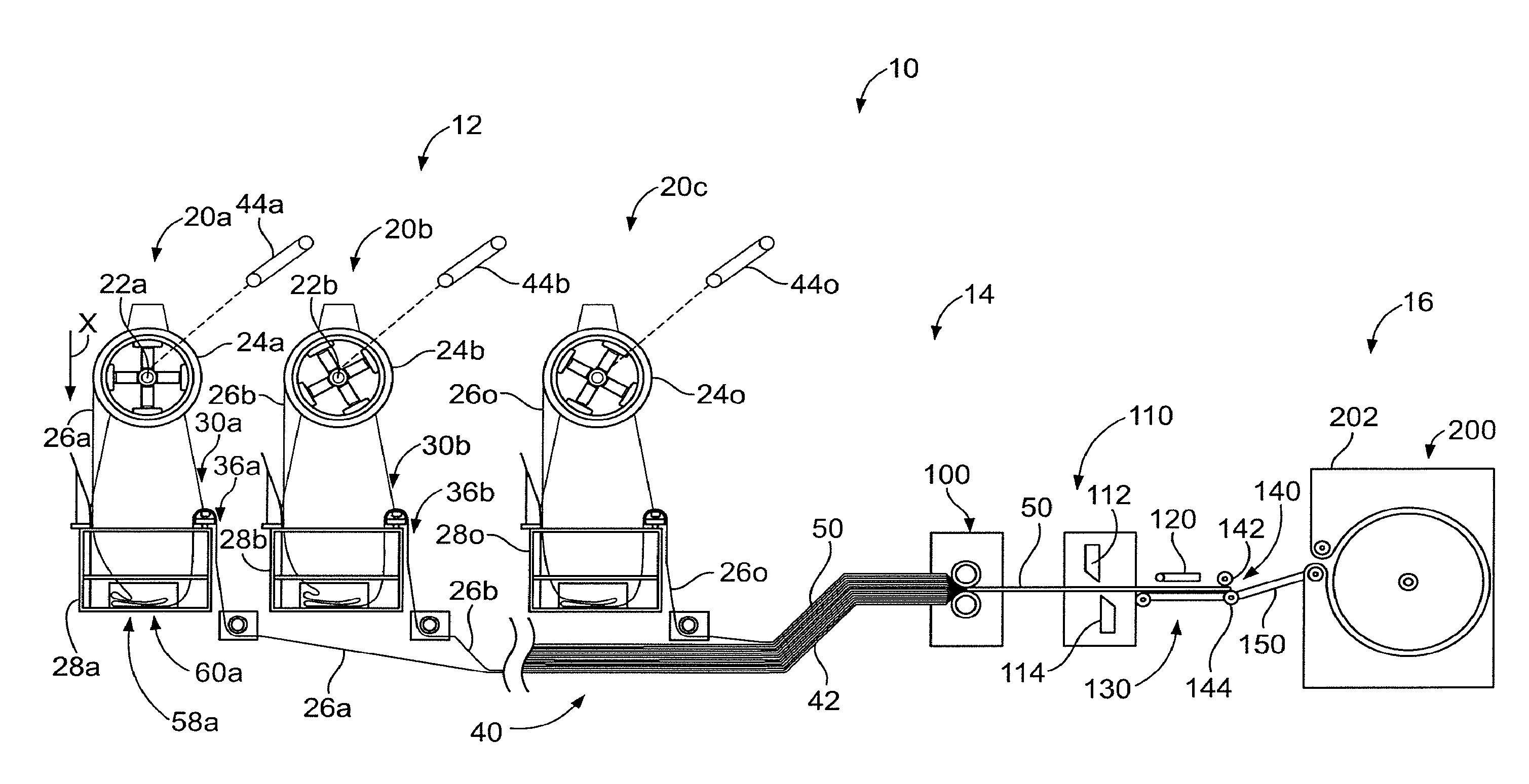
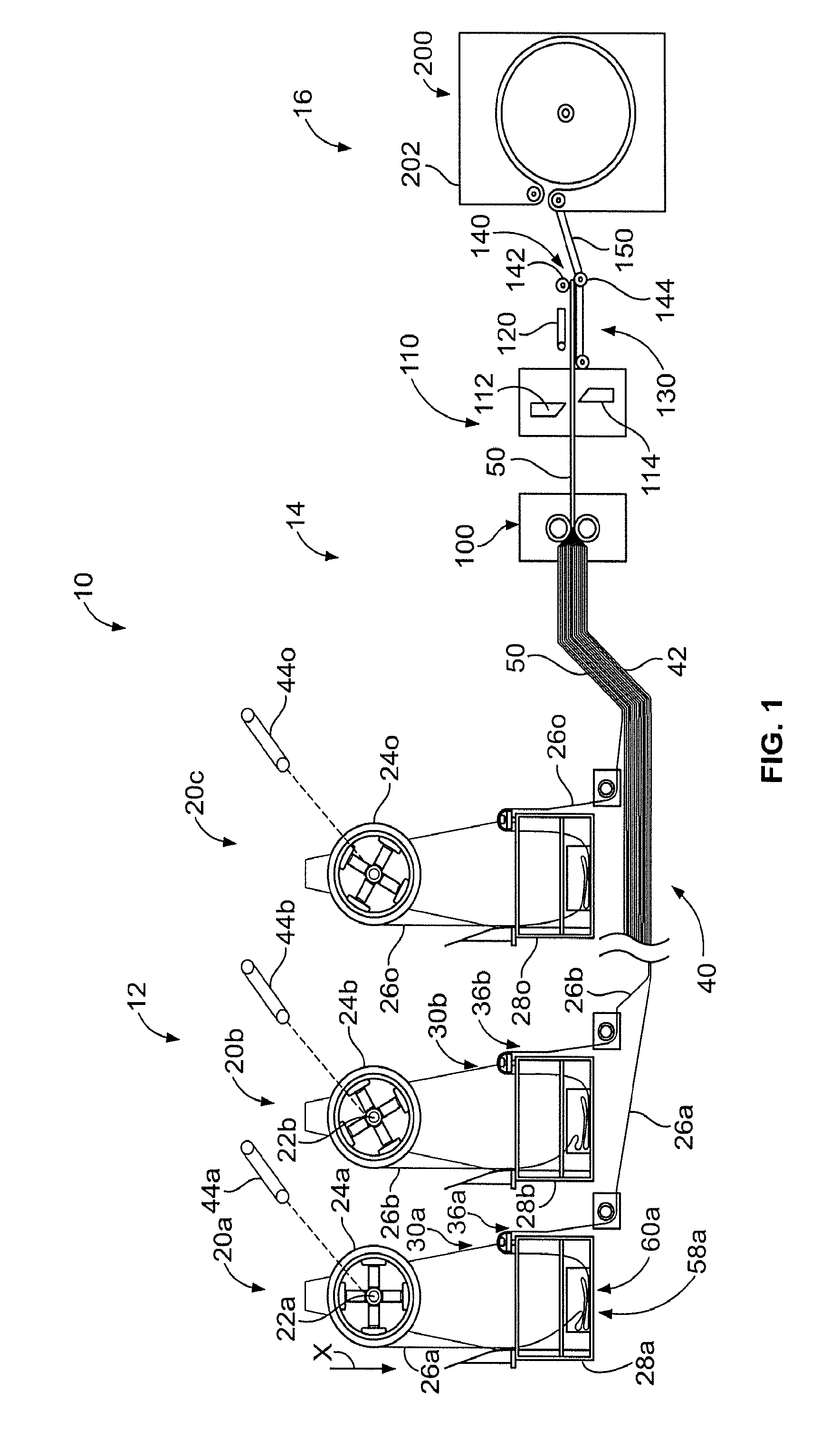
[0055]FIG. 1 illustrates a schematic side elevation view of an apparatus 10 used for processing a transformer core of amorphous metal strips in accordance with one aspect of the presently disclosed methods and systems. As will be described in greater detail below, the disclosed apparatus 10 may be used to assemble and process a stack or grouping of a plurality of amorphous strips, such as the grouping or stack of amorphous metallic strips 400 as illustrated in FIGS. 20 and 21.

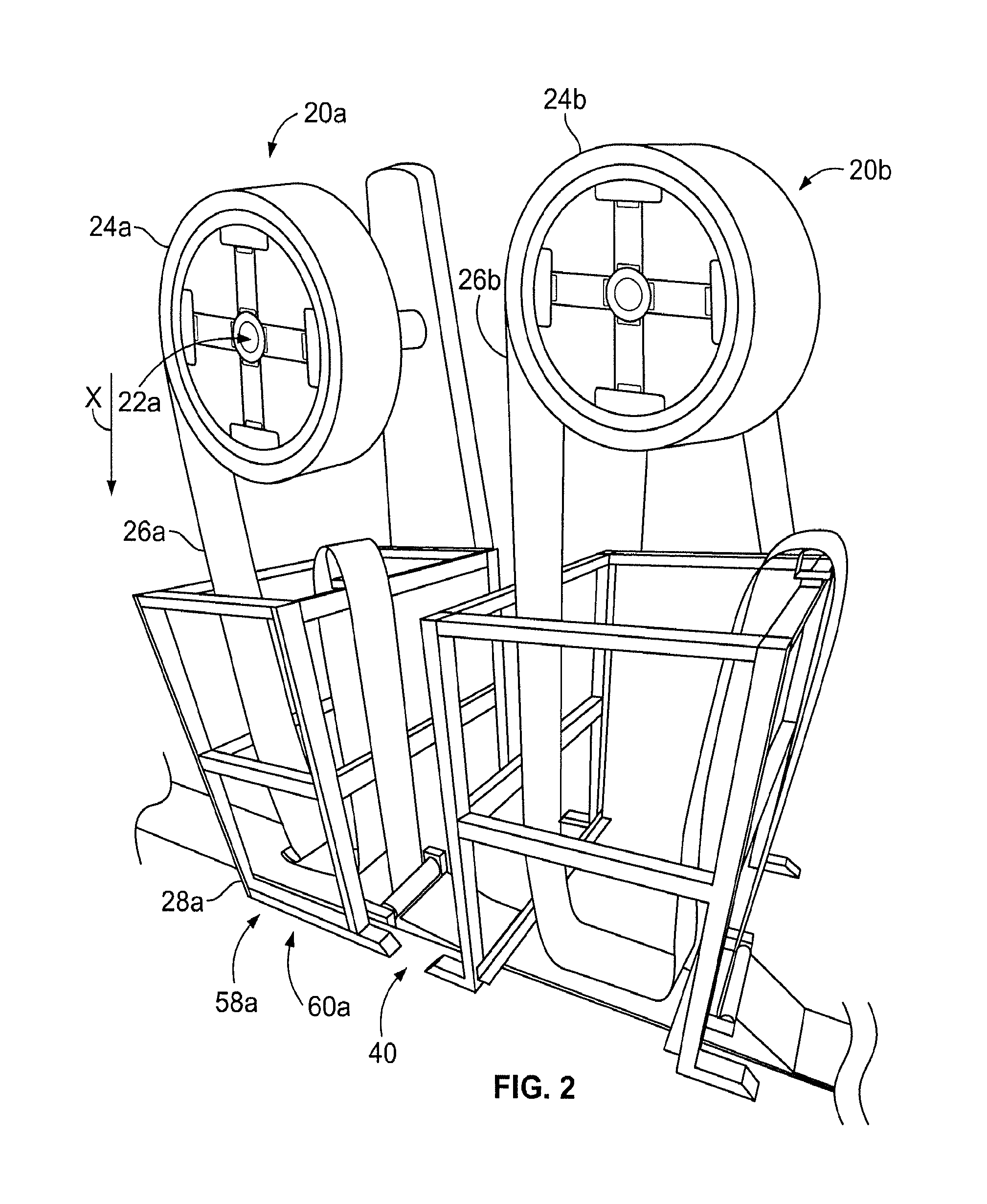
[0056]As illustrated, the apparatus 10 comprises essentially three processing sections: an unwinding section 12, a shearing section 14, and a core winding section 16. In this illustrated embodiment of apparatus 10, the unwinding section 12 preferably comprises a plurality of uncoilers 20(a-o), a plurality of spools 24(a-o), and a common strip collection tray 40. In one preferred arrangement, this common strip collection tray 40 begins at the first uncoiler 20a and ends with a ramp 42 that allows a composite str...


PUM

PropertyMeasurementUnit
thicknessaaaaaaaaaa
thicknessaaaaaaaaaa
temperaturesaaaaaaaaaa

Abstract

According to an exemplary embodiment, an apparatus for assembling an amorphous metallic transformer core from a plurality of amorphous metallic strip packets comprises an unwinding section comprising a plurality of uncoilers. Each of the plurality of uncoilers operated to unwind a coil comprising a single-ply continuous strip of a metallic material. A collection tray is configured to transport a composite metallic strip from the unwinding section, the composite metallic strip comprising a plurality of single ply metallic strips that are unwound from the plurality of uncoilers of the unwinding section. A shearing section operably coupled to the collection tray and configured to receive the composite metallic strip from the unwinding section, the shearing section configured to shear the composite metallic strip into a plurality of packets, the shearing section comprising an accumulator for holding the plurality of the packets of the composite metallic strips. A winding section is configured to receive the plurality of the packets of the composite metallic strips from the shearing section, the winding section forming a metallic transformer core from the plurality of packets of the composite metallic strips.

Description

CROSS-REFERENCE[0001]This application claims priority to U.S. Provisional Patent Application Ser. No. 61 / 779,716 filed Mar. 13, 2013, incorporated herein by reference.BACKGROUND[0002]1. Field of the Present Patent Application[0003]The present patent application is generally directed to a transformer core comprising a plurality of amorphous metal strips. Specifically, the present patent application is generally directed to a method and apparatus for making an electric transformer core comprising a plurality of metallic strip packets or groups, each packet or group may comprise a plurality of thin amorphous metal strips. These thin strips of amorphous metal are arranged in a collection of packets or groups comprising multiple-strip lengths. These collections are then arranged to surround a window of a core of the transformer where the window of the core first resides on a winder. However, aspects of the present application may be equally applicable in other scenarios as well.[0004]2. ...

Claims


Application Information

Patent Timeline
Patent Type & Authority Applications(United States)
IPC IPC(8): H01F41/02
CPCH01F41/0226Y10T29/49075Y10T29/49078
Inventor LOOBY, KEVIN, C.
Owner ERMCO COMPONENTS INC
Learn More