
Continuous embolic coil and methods and devices for delivery of the same

Active Publication Date: 2016-01-28
ENDOSHAPE INC
View PDF13 Cites 0 Cited by
  • Summary
  • Abstract
  • Description
  • Claims
  • Application Information

AI Technical Summary

Benefits of technology

The patent describes an occlusion system for targeting a specific area in a body vessel or filling an aneurysmal space. The system includes a continuous embolic coil and a delivery device for deploying the coil at the target site. The delivery device has a cutting mechanism for cutting the coil to a desired length and a delivery sheath for positioning the coil. The system can also include a second tubular body for rotating and cutting the coil. The technical effects of the system include improved occlusion and the ability to target specific areas in the body vessel or aneurysmal space with greater precision.

Problems solved by technology

This is very costly, requires considerable x-ray exposure to both physician and patient, and the resulting metal mass can detrimentally affect post procedure patient imaging with either CT or MR scanning.
After slowing the blood flow, over time, a clot forms around the embolic coil and blood flow through the section is completely blocked.
Embolic coils are also known for challenges in achieving precise vascular placement.
Using coils for embolization can present other unique challenges.
Voids in the coil pack, developed either during the procedure or post-operatively, can cause channels and resulting blood flow in an unintended area.
The sequential use of independent coils of fixed lengths can be a very time consuming procedure where the intended target is a large vessel.
However, the challenges of deploying one additional coil to further increase the coil pack density may not be deemed desirable given the coil cost and time involved with placement.
In addition, independent embolic coils can be easily misplaced.
Accordingly, coils can easily be misplaced should the initial coil not land correctly or be slightly undersized to the target vessel and slip beyond the target location.
While these devices have been employed clinically for years and the technique is generally accepted, coils present significant challenges when attempting to embolize in a very precise or limited section of vasculature.
However, due to the porosity of the mesh basket and the lack of the polymeric fibers used in coils, the metal mesh plugs have been shown to take longer to achieve occlusion than a properly placed embolic coil pack.
Further, the fixed shape of these devices makes them unattractive for use in odd-shaped spaces such as an aneurysm sack that occurs behind an endograft stent.
Further, these metal mesh devices are relatively stiff due to their construction and have limited ability to traverse sharp turns found in catheters that have been placed in a highly tortuous vascular path.
However, when the mesh is collapsed, it elongates and becomes a fairly rigid tubular structure.
Thus, while being capable of entry into a small delivery catheter, metal mesh devices have limited ability to traverse sharp turns found in catheters that have been placed in a highly tortuous path to reach the target vessel for occlusion.
Subsequently, the advantages of a single occlusion device are offset by the slow and incomplete occlusion performance and the limited application to occlusion target sites that are less tortuous to access.

Method used


Image

  • Continuous embolic coil and methods and devices for delivery of the same
  • Continuous embolic coil and methods and devices for delivery of the same
  • Continuous embolic coil and methods and devices for delivery of the same

Examples


Embodiment Construction

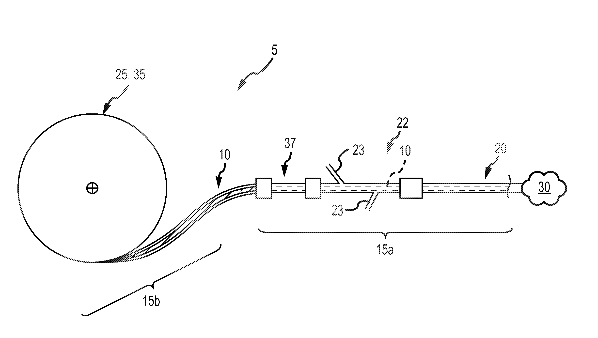
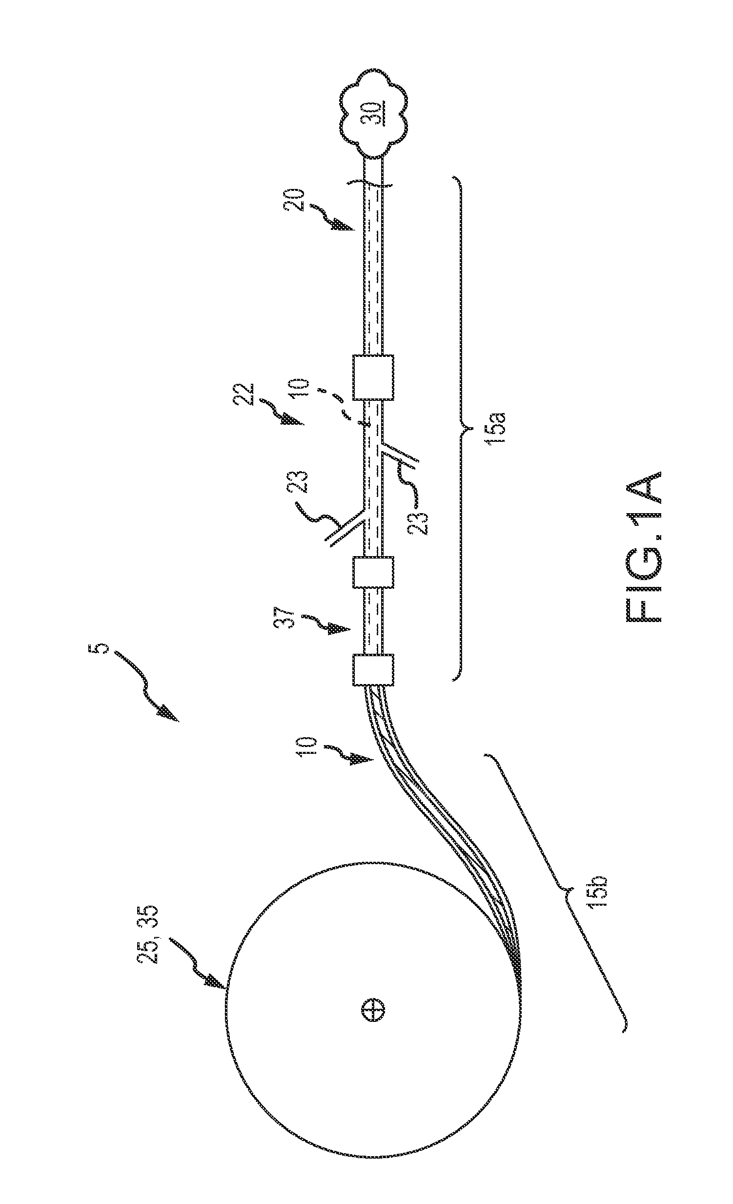
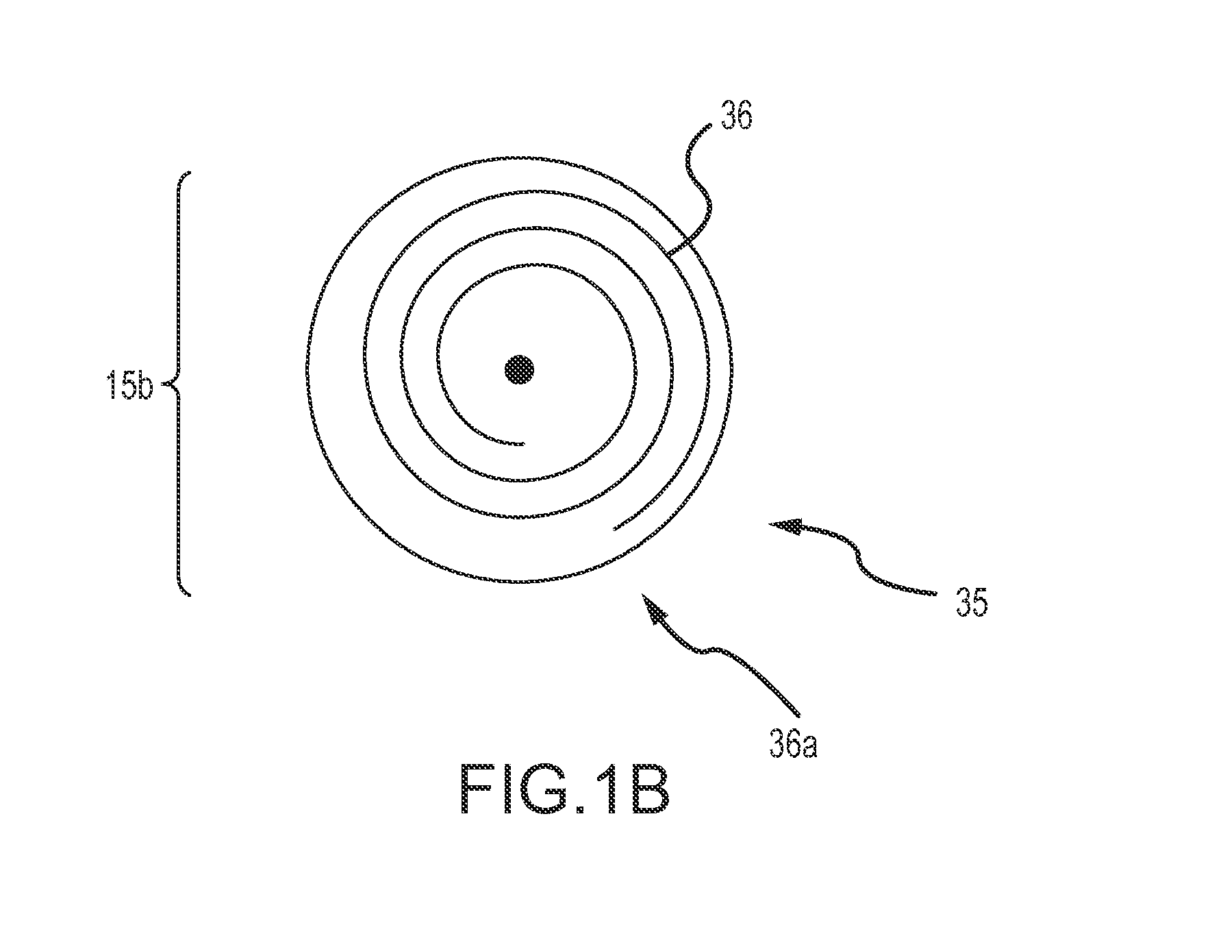
[0039]The target anatomy for vascular occlusion (e.g., internal hemorrhage, tumor isolation, aneurysms, AVMs, etc.) present significant anatomical variability and in many cases, accessing this target anatomy requires a significantly tortuous vascular path in which the delivery catheter or delivery sheath has been placed by a physician, such as an interventional radiologist, before deployment of the occlusion device or continuous embolic coil. The occlusion device or continuous embolic coil enters the tubular delivery body, such as a delivery catheter, outside the patient's body and travels down the delivery body to be deployed (expelled) into the target vessel location or aneurysmal space (i.e. the target occlusion site). At that point, the occlusion device or continuous embolic coil forms an expanding coil pack so as to occlude the vessel or fill the space. Therefore, a clinically acceptable occlusion device or continuous embolic coil is flexible to translate along the delivery bod...


PUM


Abstract

An occlusion system (5) provides a trimmable continuous embolic coil (10) that is “cut to length” at the end of its deployment into the target occlusion site. A delivery device (15) provides the “cut to length” feature for the continuous embolic coil.

Description

CROSS REFERENCE TO RELATED APPLICATIONS[0001]This application claims the benefit of priority of U.S. Application No. 61 / 779,360, filed Mar. 13, 2013 and entitled Continuous Embolic Coil and Methods and Devices for Delivery of the Same, which is hereby incorporated by reference as though fully set forth herein.[0002]The following applications are related to the present disclosure: PCT / US11 / 046829, filed Aug. 8, 2011 and entitled “Radiopaque Shape Memory Polymers for Medical Devices”; and U.S. patent application Ser. No. 13 / 262,546 filed Sep. 30, 2011 and entitled “Vascular Occlusion Devices”, each of which are hereby incorporated by reference as though fully set forth herein.TECHNICAL FIELD[0003]The disclosure relates generally to implantable devices for therapeutic treatment, and more particularly relates to an endoluminally delivered device for vascular occlusion and methods and devices for delivery of the same.BACKGROUND[0004]During many clinical procedures, a physician requires t...

Claims


Application Information

Patent Timeline
IPC IPC(8): A61B17/12
CPCA61B17/12145A61B17/12031A61B2017/00367A61B2017/00867A61B2017/12054A61B17/12113A61B17/12109A61B17/12118A61B2017/0053A61B2017/00871A61B2090/3966
Inventor CASTLEBERRY, JEFFREYALDRICH, WILLIAMBARKENBUS, CHARLESNEEDLE, STAN
Owner ENDOSHAPE INC
Learn More