Biomass pyrolysis apparatus, and power generation system

a technology of biomass pyrolysis and biomass, which is applied in the direction of lighting and heating apparatus, combustion types, machines/engines, etc., can solve the problem of low energy density of biomass, compared to fossil fuels and the like, and achieve the effect of effectively using the heat quantity of woody biomass

Active Publication Date: 2016-01-28
MITSUBISHI HEAVY IND ENVIRONMENTAL & CHEM ENG CO LTD
View PDF12 Cites 8 Cited by
  • Summary
  • Abstract
  • Description
  • Claims
  • Application Information

AI Technical Summary

Benefits of technology

[0026]According to the present invention, substantially all of the heat quantity of the woody biomass supplied to the pyrolysis gasification furnace can be utilized i

Problems solved by technology

Biomass, compared to fossil fuels an

Method used


Image

  • Biomass pyrolysis apparatus, and power generation system
  • Biomass pyrolysis apparatus, and power generation system
  • Biomass pyrolysis apparatus, and power generation system

Examples


Embodiment Construction

[0029]The following describes in detail an embodiment of the present invention, with reference to the drawings.

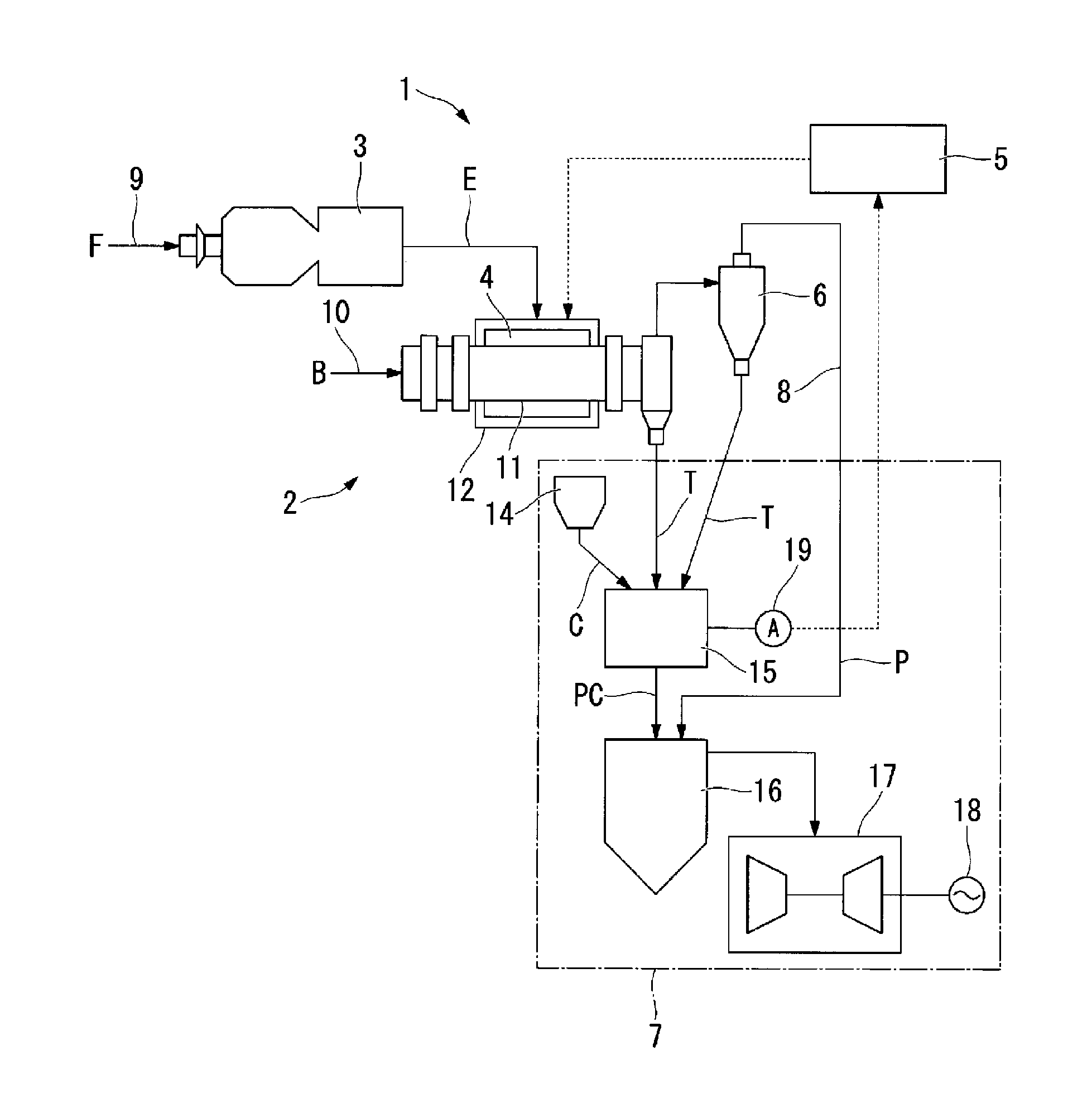
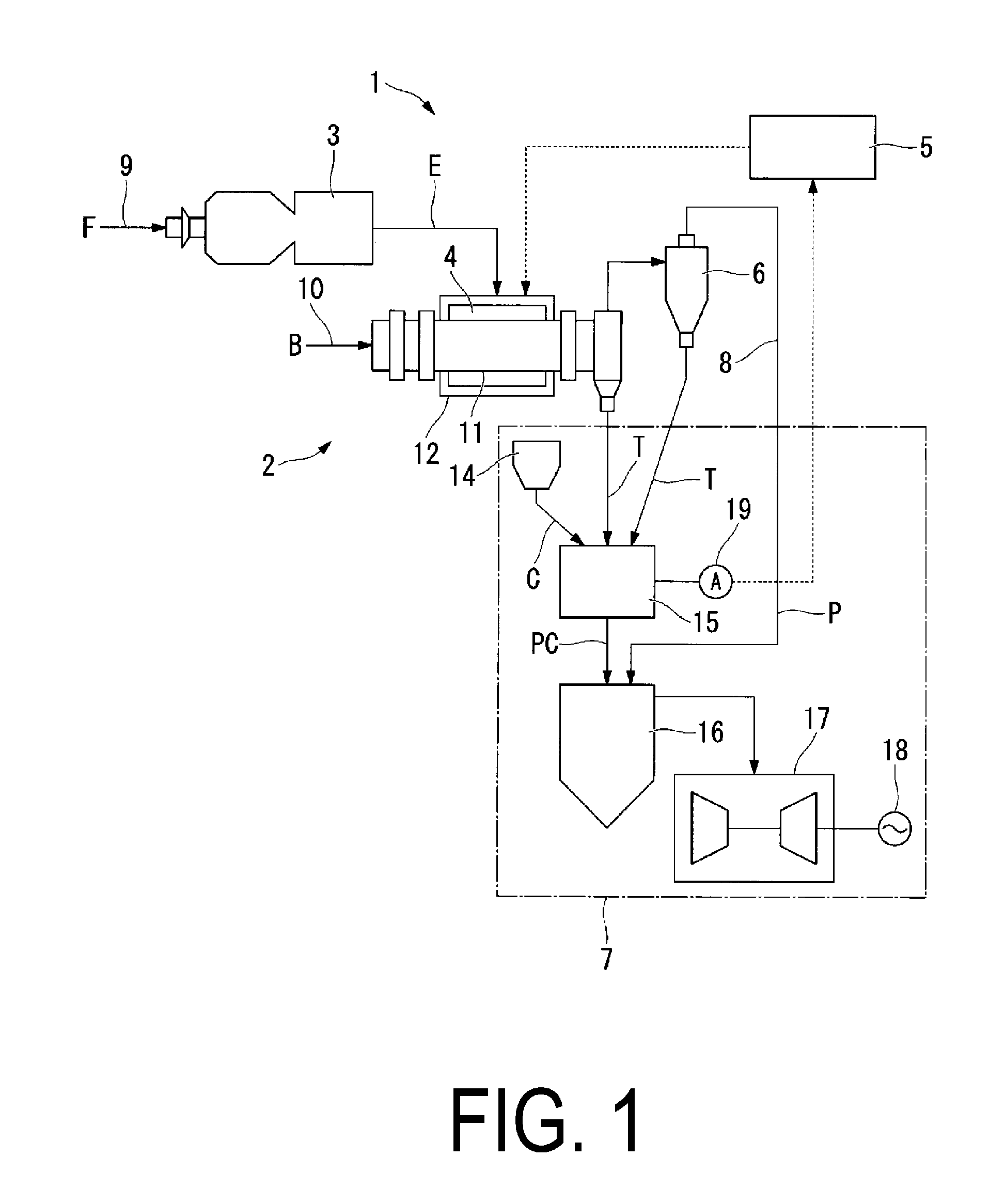
[0030]As shown in FIG. 1, a coal-fired thermal power generation system 1 of this embodiment includes the combustion furnace 3 that produces the combustion exhaust gas E by causing the stable property fuel F serving as an auxiliary fuel to combust, the pyrolysis gasification furnace 4 (carbonization furnace) that pyrolyzes the woody biomass B, a control device 5 that controls a temperature of the pyrolysis gasification furnace 4, the cyclone 6 that separates and removes the torrefied material T from within the pyrolysis gas P produced in the pyrolysis gasification furnace 4, and a coal-fired power plant 7 that generates power utilizing the torrefied material T and the pyrolysis gas P obtained in the pyrolysis gasification furnace 4.

[0031]It should be noted that the cyclone 6 may be omitted.

[0032]The stable property fuel F serving as a fuel in which the properties of coal and...


PUM


Abstract

Provided is a biomass pyrolysis apparatus comprising: a combustion furnace that produces a heat quantity by causing a stable property fuel to combust; a pyrolysis gasification furnace that produces a torrefied material, and a pyrolysis gas by pyrolyzing woody biomass by a heat quantity produced by the combustion furnace; and a pyrolysis gas introduction passage that introduces the pyrolysis gas from the pyrolysis gasification furnace into a boiler, into which the torrefied material is introduced.

Description

RELATED APPLICATIONS[0001]The present application is a National Phase of International Application No. PCT / JP2014 / 058546, filed Mar. 26, 2014, which claims priority to Japanese Application Nos. 2013-082232, filed Apr. 10, 2013.TECHNICAL FIELD[0002]The present invention relates to a biomass pyrolysis apparatus that produces a torrefied material and a pyrolysis gas by pyrolyzing woody biomass, and a power generation system provided therewith.BACKGROUND ART[0003]The gasification of biomass, such as woody biomass, in a pyrolysis gasification system and conversion of the biomass, which has been conventionally treated as waste, into resources for effective use has been in demand. Biomass, compared to fossil fuels and the like, is low in energy density. One known method for increasing the energy density of biomass is a torrefied method in which most of a heat quantity in a woody biomass is caused to remain, and a fiber portion (cellulose and lignin) contained in the woody biomass is therma...

Claims


Application Information

Patent Timeline
IPC IPC(8): C10B53/02C10B37/00C10B41/00C10B47/28C10L5/44C10L9/08F01K11/02
CPCC10B53/02C10L9/083C10L5/442C10B47/28C10B41/00C10L2290/58F01K11/02C10L2200/0469C10L2290/02C10L2290/06C10B37/00C10B47/30Y02E50/10Y02E20/12Y02E50/30F01K13/00F23G5/006F23G5/0273F23G5/20F23G5/46F23G2201/303F23G2201/304F23G2206/203F23G2209/26
Inventor ENDOU, YUUKIYAMAMOTO, HIROTAMIISHIKAWA, KEIICHI
Owner MITSUBISHI HEAVY IND ENVIRONMENTAL & CHEM ENG CO LTD
Why Eureka
Try Eureka