Projection Exposure System, Beam Delivery System and Method of Generating a Beam of Light

a beam delivery system and beam technology, applied in the direction of instruments, photomechanical equipment, active medium materials, etc., can solve the problems of non-homogeneous intensity of imaging light in a plane, reduce the imaging performance of the projection exposure system, etc., to achieve uniform light intensity and reduce speckle contrast

Inactive Publication Date: 2008-09-18
CARL ZEISS SMT GMBH
View PDF19 Cites 21 Cited by
  • Summary
  • Abstract
  • Description
  • Claims
  • Application Information

AI Technical Summary

Benefits of technology

[0037]Such reduced speckle contrast in the light illuminating the patterning structure has a particular advantage in generating a substantially uniform light intensity in the object plane of the projection optical system.

Problems solved by technology

It has been observed that, due to the spatial coherence of the laser light, interferences of the laser light result in a non-homogeneous intensity of the imaging light in a plane where the patterning structure is disposed.
Such non-homogeneous distribution of intensity of light, which is also known as speckle noise, may result in a reduced imaging performance of the projection exposure system.

Method used


Image

  • Projection Exposure System, Beam Delivery System and Method of Generating a Beam of Light
  • Projection Exposure System, Beam Delivery System and Method of Generating a Beam of Light
  • Projection Exposure System, Beam Delivery System and Method of Generating a Beam of Light

Examples


Embodiment Construction

[0054]In the exemplary embodiments described below, components that are alike in function and structure are designated as far as possible by alike reference numerals. Therefore, to understand the features of the individual components of a specific embodiment, the descriptions of other embodiments and of the summary of the invention should be referred to.

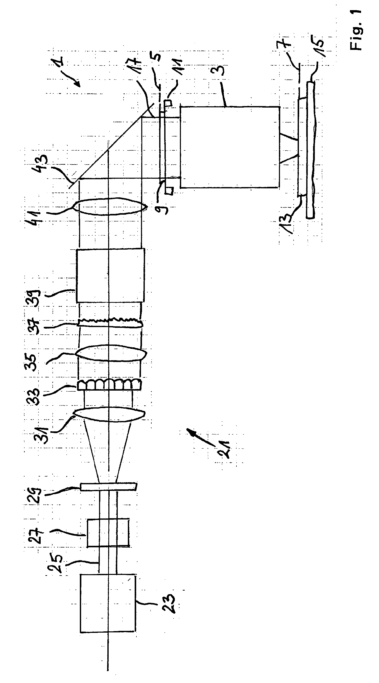
[0055]FIG. 1 schematically illustrates a projection exposure system 1. The projection exposure system 1 comprises a projection optical system 3 comprising a plurality of lenses or mirrors for imaging an object plane 5 of the projection optical system 3 onto an image plane 7 of the projection optical system 3. A reticle 9 is mounted by a reticle stage 11 such that a pattering structure provided by the reticle 9 is disposed in the object plane 5. A wafer 13 is mounted on a wafer stage 15 such that a light sensitive resist provided on a surface of the wafer 13 is disposed in the image plane 7. The patterning structure of the reticle 9 i...


PUM

PropertyMeasurementUnit
angleaaaaaaaaaa
refractive indexaaaaaaaaaa
optical delayaaaaaaaaaa

Abstract

A beam delivery system of a projection exposure system comprises a laser generating a beam of laser light from a plurality of longitudinal laser modes in a cavity, wherein light generated by a single longitudinal laser mode has an average line width λlat, wherein the laser light of the beam has, at each of respective lateral positions of the beam, a second line width λlat corresponding to lateral laser modes, and wherein the laser light of the beam has, when averaged over a whole cross section thereof, a line width λb corresponding to plural lateral laser modes, and wherein λmlatb, and wherein an optical delay apparatus disposed in the beam provides an optical path difference Δl, wherein
0.8·λ02(2·Δλl)<Δl<1.8·λ02(2·Δλl),
wherein λ0 is an average wavelength of the light of the first beam of laser light, and Δλlat represents the second line width.

Description

BACKGROUND OF THE INVENTION[0001]1. Field of the Invention[0002]The present invention relates to a method of generating a beam of light, a beam delivery system and a projection exposure system for imaging a patterning structure onto a light sensitive substrate.[0003]2. Brief Description of Related Art[0004]Lithographic processes are commonly used in the manufacture of miniaturized structures, such as integrated circuits, liquid crystal elements, micro-patterned structures and micro-mechanical components.[0005]A projection exposure system used for photolithography generally comprises a projection optical system for imaging a patterning structure, commonly referred to as a reticle, onto a substrate, commonly referred to as a wafer. The substrate is coated with a photosensitive layer, commonly referred to as a resist, which is exposed with an image of the patterning structure using imaging light. The imaging light is generated by a beam delivery system illuminating the patterning struc...

Claims


Application Information

Patent Timeline
Patent Type & Authority Applications(United States)
IPC IPC(8): G03F7/20H01S3/08H01S3/03
CPCB82Y10/00G03F7/70583G03F7/70166G03F7/70025G03F7/70191G03F7/2053H01L21/0274
Inventor KUSS, MATTHIASFIOLKA, DAMIANREISINGER, GERDMAUL, MANFREDDAVYDENKO, VLADIMIR
Owner CARL ZEISS SMT GMBH
Why Eureka
Try Eureka