System And Apparatus For Integrated HVACR And Other Energy Efficiency And Demand Response

Inactive Publication Date: 2016-01-28
PACECONTROLS
View PDF7 Cites 11 Cited by
  • Summary
  • Abstract
  • Description
  • Claims
  • Application Information

AI Technical Summary

Benefits of technology

The present invention meets the need for an electronic controller that automatically controls and manages the operation of energy-consuming equipment powered by alternating electrical power current. It includes a controller switch, a digital recycle counter, a digital timer, a learning module, an external conditioning device, and an auctioneering control signal device. The learning module analyzes input information and derives algorithms to optimize energy use and demand of the load unit. The external conditioning device senses physical values related to the load unit cycle or temperature of the space and provides feedback signals. The auctioneering control signal device selects a highest or lowest value from the input signals and outputs it as an auctioneered control signal to the controller switch. This innovation allows for improved heat transfer in the evaporator and can optimize burner operation in gas-, oil- and propane-fired heating equipment.

Problems solved by technology

Although some of these improvements can be found on many units of new HVAC&R equipment, there is a large installed base of older existing equipment still in operation but often unable to take advantage of these energy related improvements as retrofit improvements.
It is often difficult to retrofit existing installations with these methodologies because the methodologies are highly dependent on the HVAC&R equipment, configuration, and installation details.
Adding a conventional energy saving methodology to an existing HVAC&R system can be costly and time consuming.

Method used


Image

  • System And Apparatus For Integrated HVACR And Other Energy Efficiency And Demand Response
  • System And Apparatus For Integrated HVACR And Other Energy Efficiency And Demand Response
  • System And Apparatus For Integrated HVACR And Other Energy Efficiency And Demand Response

Examples


Embodiment Construction

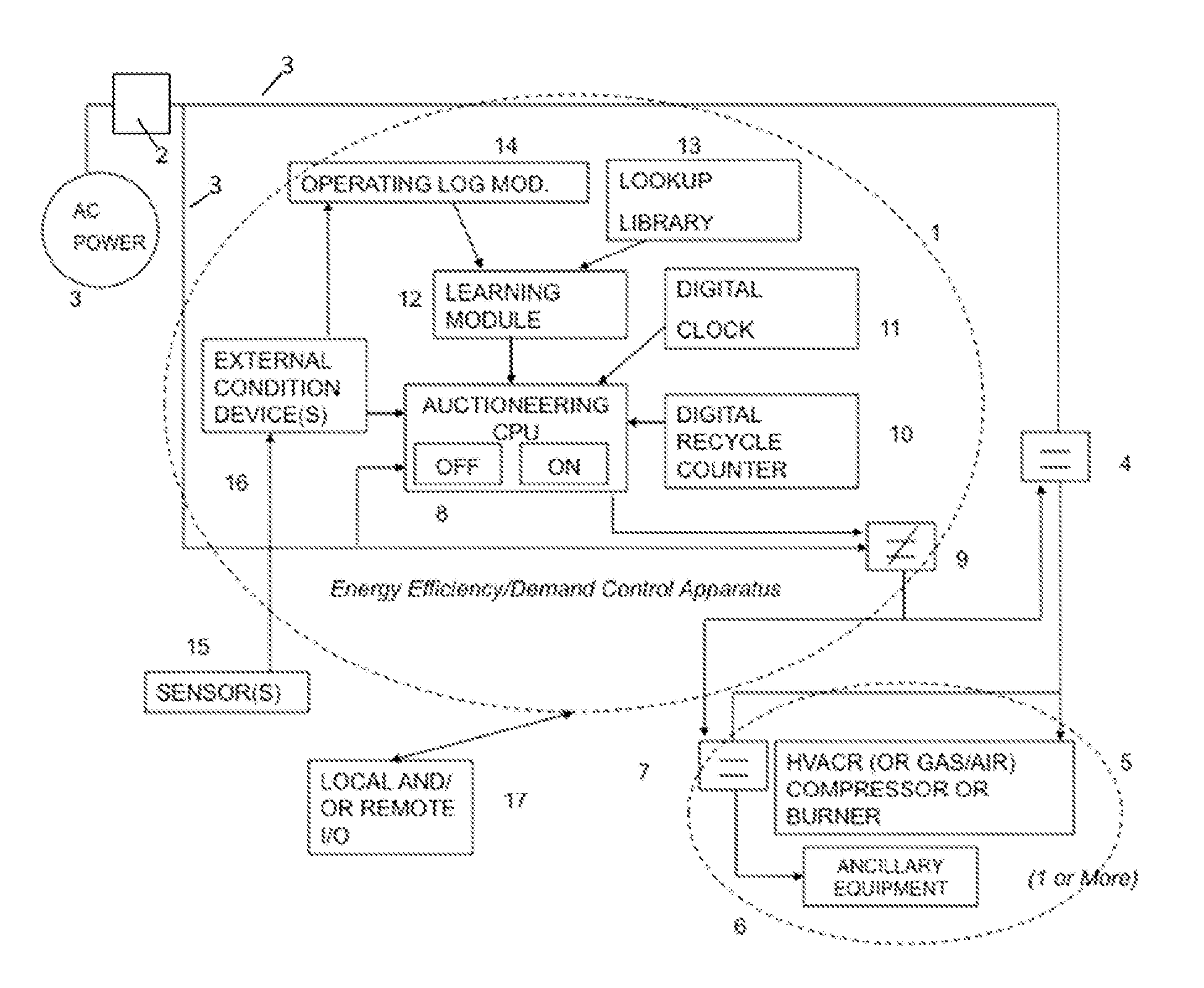
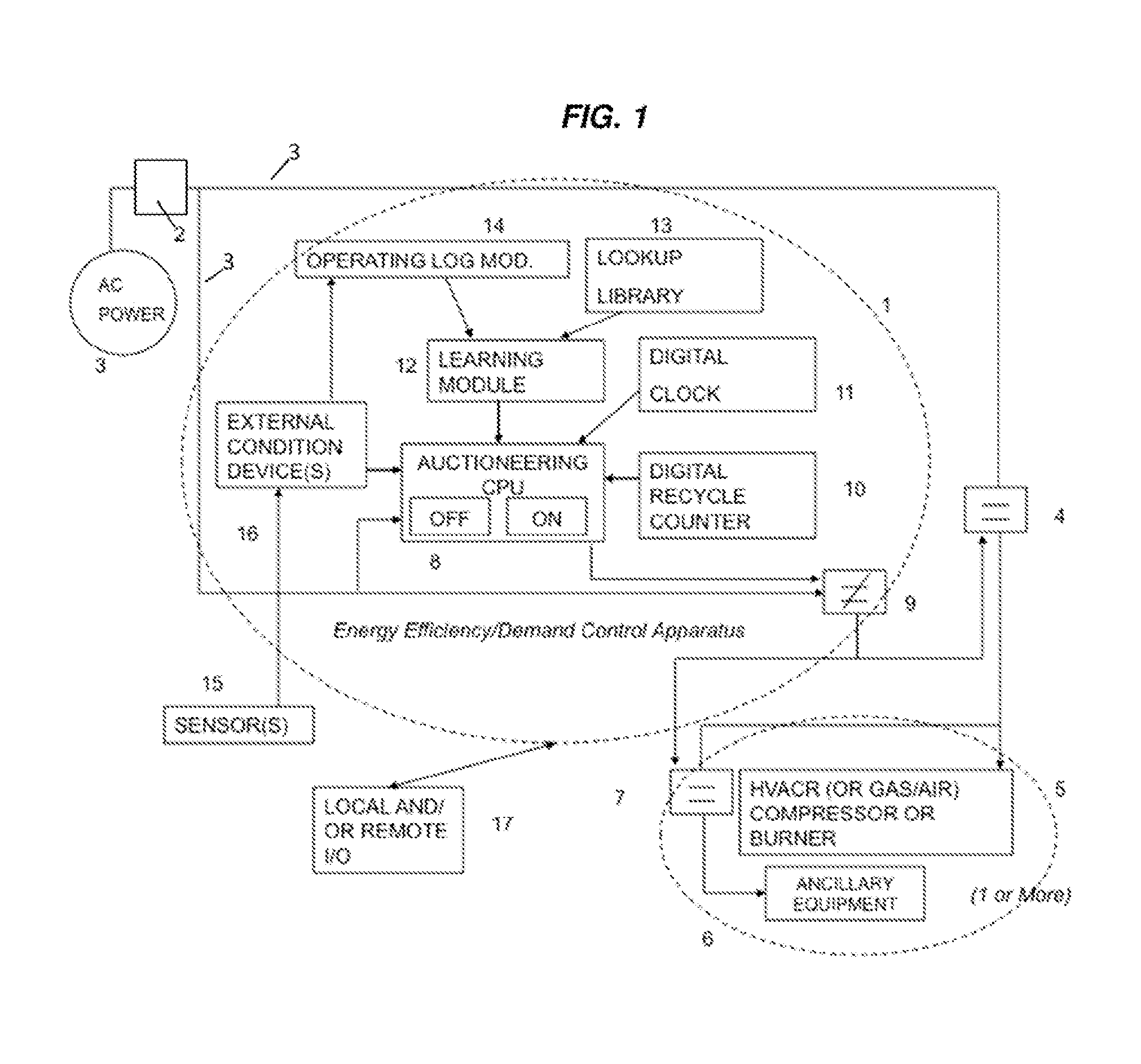
[0020]The present invention relates in part to an electronic controller apparatus for providing automatic control in an HVAC&R system or other electrically controlled cooling and / or heating systems, and / or a gas compression or compressed air system, and the like. The controller apparatus of the present invention can comprise the units enclosed within the dashed oval 1 in FIG. 1, labeled “Energy Efficiency / Demand Control Apparatus”. With reference to FIG. 1, AC power is supplied through power lines 3 via AC power meter 2, which measures electrical energy usage and demand of electrical energy at that location. Through load unit control switch 4, the AC power supplies an energy-consuming load unit 5—in the examples provided, an HVAC&R compressor or burner, or gas compression / compressed air compressor. The AC power also can supply ancillary equipment 6, through ancillary equipment control switch 7.

[0021]In the apparatus of the present invention within oval 1, the auctioneering central p...


PUM


Abstract

Electronic controller apparatus for automatically controlling and managing load demand and operation of energy-consuming equipment powered by alternating electrical power current, whereby feedback signals from a vapor compression evaporator or other source, and possibly other physical signals, are used to supplement the pre-fixed, learned, or default settings to optimize compressor operation (run time) in cooling and refrigeration equipment, and thereby to improve heat transfer in the evaporator. The effect is to improve the Energy Efficiency Ratio (EER), Seasonal Energy Efficiency Ratio (SEER), and Coefficient of Performance (COP) for the unit, and provide other advantages and improvements. In gas-, oil-, and propane-fired HVAC&R heating systems, the apparatus can also optimize burner operation and thereby improve heat transfer across the burner heat exchanger. HVAC&R systems that incorporate the demand controller and methods of their operation also are provided. The apparatus can also be applied to gas compression and compressed air control systems.

Description

BACKGROUND OF THE INVENTION[0001]This application claims the benefit under 35 U.S.C. §119(e) of prior U.S. Provisional Patent Application No. 61 / 799,501, filed Mar. 15, 2013, which is incorporated in its entirety by reference herein.[0002]The present invention relates to a system and apparatus for automatically controlling and optimizing electrically controlled energy-consuming equipment, including gas-, oil-, and propane-fired heating equipment controlled via electrically powered control systems. The present invention also relates to heating, ventilating, air conditioning, and refrigeration equipment systems incorporating the apparatus and methods of using the apparatus in such systems.[0003]Heating, ventilating, air conditioning and / or refrigeration (“HVACR” or “HVAC&R”) control systems have been designed to perform two major functions: temperature regulation and dehumidification. Increased focus on carbon footprint and green technologies has led to numerous energy related improve...

Claims


Application Information

Patent Timeline
IPC IPC(8): F24F11/00G05B13/02H02J3/14
CPCF24F11/006H02J3/14G05B13/0265F24F11/30F24F11/62H02J2203/20H02J2310/12H02J2310/14F24F11/61F24F11/46F24F11/63F24F2140/00Y02B70/3225Y04S20/222Y02E40/70Y02E60/00Y04S10/50Y04S40/20
Inventor MILLS,, JR., THOMAS A.BUDNEY, STANLEY
Owner PACECONTROLS
Why Eureka
Try Eureka