Illumination System, Inspection Apparatus Including Such an Illumination System, Inspection Method and Manufacturing Method

a technology of illumination system and inspection apparatus, applied in the direction of photometry, instruments, electric discharge lamps, etc., can solve the problems of layout difficulties, vibration and wear, and devices that have not been implemented for illumination systems, and achieve the effect of greater freedom of control

Active Publication Date: 2016-01-28
ASML NETHERLANDS BV
View PDF10 Cites 33 Cited by
  • Summary
  • Abstract
  • Description
  • Claims
  • Application Information

AI Technical Summary

Benefits of technology

[0013]The present invention aims to provide alternative illumination systems for metrology and other applications in which an illumination profile can be selected by a programmable device, without some of the compromises that would otherwise result. For example, the invention may maintain greater freedom to control other illumination parameters such as polarization or wavelength. For example, the invention in some embodiments aims to enable the use of liquid crystal transmissive SLM without unduly restricting polarization as an illumination parameter.
[0034]The first and second spatial light modulators may be located effectively in a pupil plane of the illumination system. In this way the amount and polarization state of radiation incident on a target from different angles of incidence may be controlled.
[0035]Alternatively or in addition, first and second spatial light modulators may be located effectively in a field plane of the illumination system. In this way, the amount and polarization state of radiation incident on different parts of a target may be controlled.

Problems solved by technology

There are several moving parts in the known illumination system, making it sensitive to vibrations and wear.
However, in practice these devices have not been implemented for the illuminator.
One reason for this may be that providing reflective programmable SLMs such as DMDs in the illumination path requires convoluted beam paths and cause layout difficulties.
A problem with LC shutter type devices is that they generally deliver only one polarization of light, while metrology applications require freedom to control polarization as an illumination parameter in the recipe.

Method used


Image

  • Illumination System, Inspection Apparatus Including Such an Illumination System, Inspection Method and Manufacturing Method
  • Illumination System, Inspection Apparatus Including Such an Illumination System, Inspection Method and Manufacturing Method
  • Illumination System, Inspection Apparatus Including Such an Illumination System, Inspection Method and Manufacturing Method

Examples


Embodiment Construction

[0061]Before describing embodiments of the invention in detail, it is instructive to present an example environment in which embodiments of the present invention may be implemented.

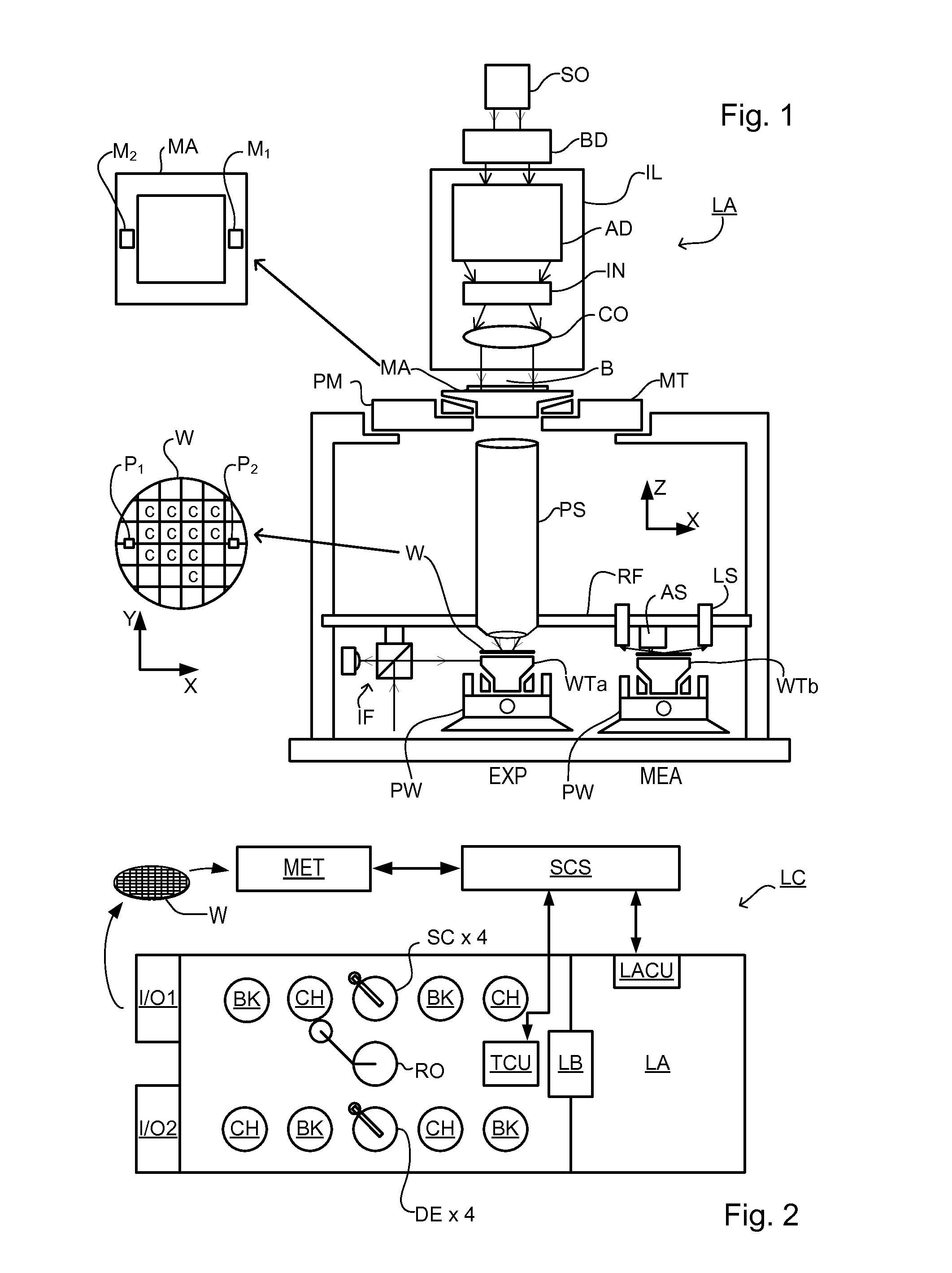
[0062]FIG. 1 schematically depicts a lithographic apparatus LA. The apparatus includes an illumination system (illuminator) IL configured to condition a radiation beam B (e.g., UV radiation or DUV radiation), a patterning device support or support structure (e.g., a mask table) MT constructed to support a patterning device (e.g., a mask) MA and connected to a first positioner PM configured to accurately position the patterning device in accordance with certain parameters; two substrate tables (e.g., a wafer table) WTa and WTb each constructed to hold a substrate (e.g., a resist coated wafer) W and each connected to a second positioner PW configured to accurately position the substrate in accordance with certain parameters; and a projection system (e.g., a refractive projection lens system) PS configured t...


PUM

PropertyMeasurementUnit
wavelengthsaaaaaaaaaa
angle of polarizationaaaaaaaaaa

Abstract

In an illumination system (12, 13) for a scatterometer, first and second spatial light modulators lie in a common plane and are formed by different portions of a single liquid crystal cell (260). Pre-polarizers (250) apply polarization to first and second radiation prior to the spatial light modulators. A first spatial light modulator (236-S) varies a polarization state of the first radiation in accordance with a first programmable pattern. Second spatial light modulator (236-P) varies a polarization state of the second radiation accordance with a second programmable pattern. A polarizing beam splitter (234) selectively transmits each of the spatially modulated first and second radiation to a common output path, depending on the polarization state of the radiation. In an embodiment, functions of pre-polarizers are performed by the polarizing beam splitter.

Description

CROSS REFERENCE TO RELATED APPLICATIONS[0001]This application claims benefit of EP Patent Application No 14178791.1, filed on Jul. 28, 2014.[0002]This application claims benefit of EP Patent Application No 14191958.9, filed on Nov. 5, 2014.BACKGROUND[0003]1. Field of the Invention[0004]The present invention relates to inspection apparatus and methods usable, for example, to perform metrology in the manufacture of devices by lithographic techniques. The invention further relates to an illumination system for use in such inspection apparatus and to methods of manufacturing devices using lithographic techniques.[0005]2. Background Art[0006]A lithographic apparatus is a machine that applies a desired pattern onto a substrate, usually onto a target portion of the substrate. A lithographic apparatus can be used, for example, in the manufacture of integrated circuits (ICs). In that instance, a patterning device, which is alternatively referred to as a mask or a reticle, may be used to gene...

Claims


Application Information

Patent Timeline
Patent Type & Authority Applications(United States)
IPC IPC(8): G02B27/28G01J1/08G01N21/47G02F1/01
CPCG02B27/283G01J1/08G01N21/47G02F1/01G01N21/8806G01N21/9501G01N2021/8848G01N2201/0675G02F1/1313G02F1/13306G03F7/70633
Inventor VAN DER ZOUW, GERBRANDJAK, MARTIN JACOBUS JOHANEBERT, MARTIN
Owner ASML NETHERLANDS BV
Why Eureka
Try Eureka