Smart wearable device

a wearable device and smart technology, applied in the field of wearable devices, can solve the problems of deteriorating the appearance unity of the smart bracelet or smart watch, easy scratching of the panel, limited area for displaying information, etc., and achieve the effect of reducing the scratch problem of the display unit, reducing the and reducing the scratch problem of the display modul

Inactive Publication Date: 2016-01-28
HANNSTAR DISPLAY NANJING +1
View PDF5 Cites 18 Cited by
  • Summary
  • Abstract
  • Description
  • Claims
  • Application Information

AI Technical Summary

Benefits of technology

[0031]As mentioned above, in the smart wearable device of this invention, because the slide-on-strap touch-sensing structures disposed on the opposite sides of the display module providing users about the touch operation, so, the finger won't shade the user's view and the image or items displayed by the display module. Therefore, the erroneous touch can be decreased and the scratch problem of the display module also can be reduced. Additionally, because the element of performing the touch operation is the slide-on-strap touch-sensing structure, the conventional physical button can be replaced. Therefore, the panel scratch problem of the display unit can be reduced, and the overall integrity and beauty of the appearance of the smart wearable device can be achieved. Furthermore, the higher quality and more wonderful user experience can be implemented.
[0032]Because the slide-on-strap touch-sensing structure of the touch input is disposed on the strap, the touch display panel needn't to be applied in, and the rare earth transparent touch-sensing layer needn't be introduced so as to cost down. Furthermore, the metal interference fringe will not happen by the metal wires, so that the readability of the display panel won't be influenced and the performance and convenience of the manual operation can be kept.
[0033]In addition, by the definition of a specific hand gesture, the user can easily implement data transmission, so as to enhance overall functionality of the slide-on-strap smart device.

Problems solved by technology

However, as to the smart bracelet and the smart watch, because the size is smaller, the area for displaying information is limited.
Although some smart watches are configured with the touch display panel so that the user can directly operate the smart watch in a touch manner, the user's view is easily shaded by the finger during the operation because the display area of the smart watch is small, and the erroneous touch will happen therefore.
However, after a long period of the touch operation on the display panel, the panel scratch problem is easily caused.
Although the physical key can reduce the erroneous touch situation, the physical key needs to be disposed on the surface of the smart bracelet or smart watch, the appearance unity of the smart bracelet or smart watch will be deteriorated.
Furthermore, the touch display panel often needs to be configured with the rare earth transparent touch-sensing layer such as ITO (indium tin oxide) so as to be kept in high transparent display performance, but since the rare earth metal indium is unceasingly consumed, the cost of the product will become higher and higher.
Besides, the conductivity of the rare earth metal is worse than the normal metal, so that the detection sensitivity of the touch is limited.
Therefore, using the rare earth transparent touch-sensing layer in the touch panel is not a good choice for the environmental resources and energy conservation.

Method used


Image

  • Smart wearable device
  • Smart wearable device
  • Smart wearable device

Examples


first embodiment

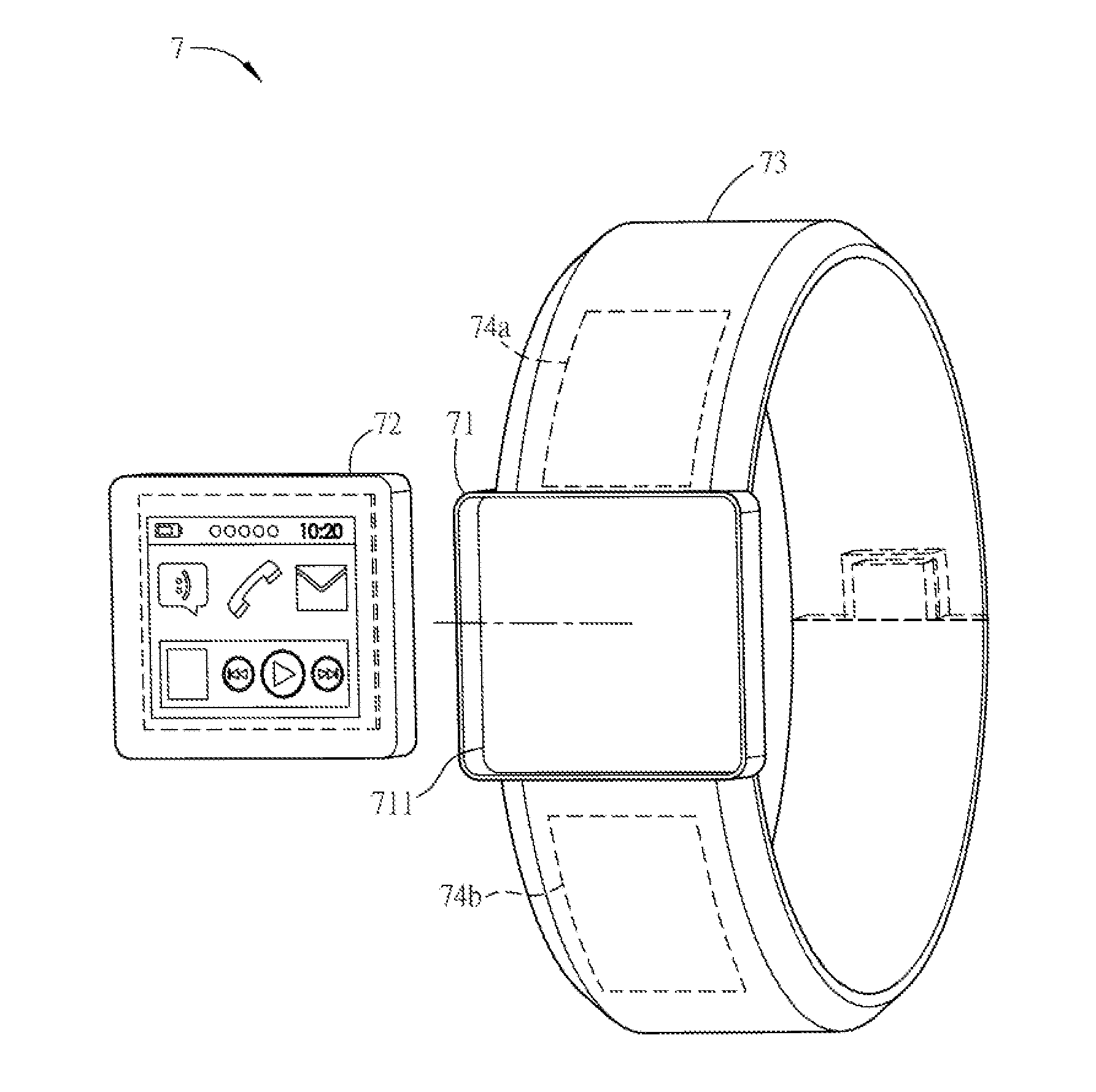
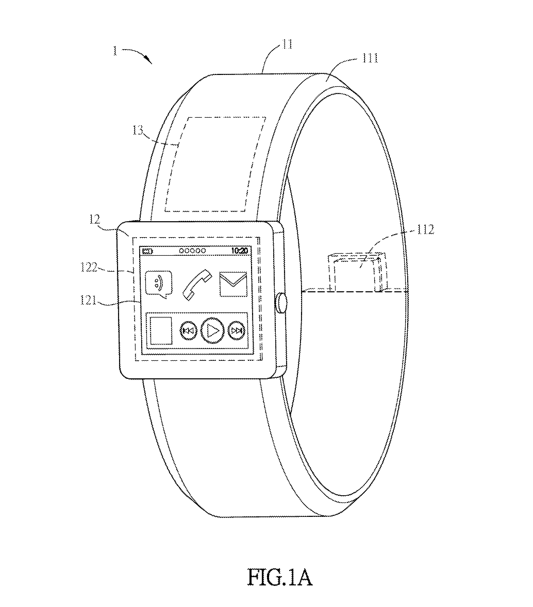
[0056]Refer to FIG. 1A, which is a schematic diagram of a smart wearable device 1 of the invention. The smart wearable device 1 of this embodiment is a smart watch to be described as an example. In addition, the elements of the smart wearable device 1 of this embodiment may be implemented by the combination of the hardware, software or firmware of one or multiple signal processing and / or integrated circuits.

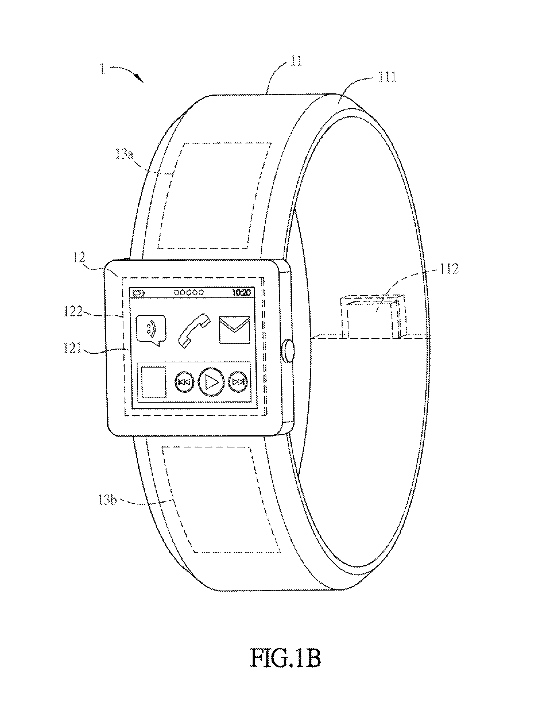
[0057]The smart wearable device 1 of this embodiment comprises a body 11, a display module 12 and at least one slide-on-strap touch-sensing structure 13. FIG. 1B is a schematic diagram of a variation of the smart wearable device of the first embodiment, wherein the smart wearable device 1 comprises two slide-on-strap touch-sensing structures 13a and 13b. The following embodiment is based on the two slide-on-strap touch-sensing structures 13a and 13b as an example. The body 11 is the portion that the user can wear and is a watchband or a strap of a bracelet in this embodiment, and...

second embodiment

[0074]FIG. 6 is a schematic diagram of a smart wearable device 2 of the invention. As shown in FIG. 6, in one embodiment, the smart wearable device 2 can further comprise at least one function unit, which is disposed on the body 21 or the slide-on-strap touch-sensing structure 23a or 23b and coupled with the processing unit 222. The function unit comprises at least one of a wireless transmission unit 25, a wireless communication unit 26 and a wireless charging unit 27.

[0075]The wireless transmission unit 25 comprises an infrared module, a Bluetooth module, a radio frequency module or a near field communication module, and the wireless transmission unit 25 of this embodiment is illustrated as a near field communication module for example. The near field communication module comprises a near field communication chip and an antenna. The near field communication chip is coupled with the processing unit 222. The antenna can be disposed on the slide-on-strap touch-sensing structure 23a an...

third embodiment

[0077]The disposition manner of the display module is not limited in this invention. In other embodiments, the display module also can be detachably disposed on the body, as shown in FIG. 7, which is a schematic diagram of a smart wearable device of the invention. In this embodiment, the body 31 further comprises a depression 313, and the display module 32 can be disposed in the depression 313.


PUM


Abstract

A smart wearable device comprises a body, a display module and at least one slide-on-strap touch-sensing structure. The display module is disposed on the body and comprises a display unit and a processing unit coupled with the display unit. The slide-on-strap touch-sensing structure is coupled with the processing unit and two slide-on-strap touch-sensing structures are disposed on the opposite sides of the display unit. The slide-on-strap touch-sensing structure senses at least one trigger event. By disposing the area of the touch input on two sides of the display unit, the image or items displayed by the display unit won't be shaded during the user's operation.

Description

CROSS REFERENCE TO RELATED APPLICATIONS[0001]This Non-provisional application claims priority under 35 U.S.C. §119(a) on Patent Application No(s). 201410361715.X, 201410359760.1 and 201410380523.3 filed in People's Republic of China on Jul. 25, 2014, Jul. 25, 2014 and Aug. 4, 2014, the entire contents of which are hereby incorporated by reference.BACKGROUND OF THE INVENTION[0002]1. Field of Invention[0003]This invention relates to a wearable device and, in particular, to a smart wearable device.[0004]2. Related Art[0005]With the progress of technologies, various information devices having communication functions are continuously innovated, such as mobile phones, tablet computers, ultra-thin notebook computers, satellite navigation devices or the like. At present, due to advances in technology, the processors are continuously developed toward the direction of the small size and the high performance. Thus some wearable devices having the sizes much smaller than other communication dev...

Claims


Application Information

Patent Timeline
Patent Type & Authority Applications(United States)
IPC IPC(8): G06F3/047G09G5/00
CPCG06F3/047G09G2300/04G09G2370/16G09G5/003G06F3/147G09G5/00G09G2354/00G06F3/04883G06F3/04842G06F1/163G06F1/1654G06F1/169
Inventor WU, HSU-HOLU, TIEN-RONG
Owner HANNSTAR DISPLAY NANJING
Why Eureka
Try Eureka