Work hardenable yield ratio-controlled steel and method of manufacturing the same

a yield ratio and hardening technology, applied in the field of steel materials, can solve the problems of reducing the yield ratio, and reducing the efficiency of cold forging non-heat-treated steel, etc., and achieves low yield ratio, low cost, and easy plastic deformation

Active Publication Date: 2016-02-04
KOREA INST OF MATERIALS SCI
View PDF13 Cites 2 Cited by
  • Summary
  • Abstract
  • Description
  • Claims
  • Application Information

AI Technical Summary

Benefits of technology

[0018]According to the present invention, a method of manufacturing yield ratio-controlled steel enables the alloy steel to be heat-treated to control the structure thereof, thereby obtaining low-yield-ratio steel. The low-yield-ratio steel can be utilized as a material for cold forging at room temperature. When the yield strength is low, plastic deformation is easily carried out, and additionally, high tensile strength can be attained using work hardenability that is controlled as necessary. Hence, it is possible to obtain products having desired strength even without the use of Q / T after forging.
[0019]Furthermore, post heat treatment can be obviated, the manufacturing costs can be remarkably decreased through simple pretreatment, moldability and workability can be improved, and the forging load can be decreased.

Problems solved by technology

Due to pre / post heat treatment and the large number of processes involved, the manufacturing cost is excessively increased, and a correction process is additionally required owing to dimensional changes attributable to heat treatment deformation, undesirably negating the energy saving and automation benefits.
Also, Non-Heat-Treated steel for cold forging has been developed, and the application thereof has been attempted, but some examples (LH85, etc.) thereof are limitedly applied to bolts.
Although this steel is advantageous because it obviates the need for Q / T after forging, the forging load may be excessively raised at a tensile strength of 80 kgf / mm2 or more, attributable to the high yield ratio thereof, undesirably shortening the lifetime of a mold, thereby making it impossible to broaden the scope of application thereof.
Furthermore, steel wires resulting from the continuous production of cold Non-Heat-Treated steel comprising a two-phase structure of ferrite and pearlite are problematic in terms of non-uniform quality because there is a significant material difference of 20% or more between the head portion and the tail portion.
In order to solve this problem, as illustrated in FIG. 2, isothermal transformation has to be additionally carried out before cold forging, which may increase material costs, making it difficult to apply.

Method used


Image

  • Work hardenable yield ratio-controlled steel and method of manufacturing the same
  • Work hardenable yield ratio-controlled steel and method of manufacturing the same
  • Work hardenable yield ratio-controlled steel and method of manufacturing the same

Examples


example 1

Manufacture of Yield Ratio-Controlled Steel (YRCS80) Through Two-Stage Heat Treatment and of Cold Forged Part (8T Bolt) Using the Same

[0050]In Example 1, a steel wire, comprising 0.15 wt % C, 1.5 wt % Mn, 1.5 wt % Si, and 0.050 wt % Al, with the remainder of Fe and unavoidable impurities, was sequentially subjected to first heat treatment at 800° C. for 20 min and then second heat treatment at 400 to 430° C. for 30 min, thus obtaining YRCS80 as yield ratio-controlled steel, which was then applied to the manufacture of a 8T bolt. The results thereof were compared with the conventional results.

[0051]FIG. 4 illustrates the microscope images of the structure of the steel before and after two-stage heat treatment according to the present invention, and FIG. 5 illustrates changes in hardness of the steel before and after two-stage heat treatment for yield ratio control, wherein hardness is increased by about 10% after the heat treatment.

[0052]As illustrated in FIG. 4, coarse structure gra...

example 2

Manufacture of Yield Ratio-Controlled Steel (YRCS100) Through Two-Stage Heat Treatment and of Cold Forged Part (10T Bolt) Using the Same

[0072]In Example 2, a steel wire, comprising 0.22 wt % C, 1.5 wt % Mn, 1.5 wt % Si, and 0.050 wt % Al, with the remainder of Fe and unavoidable impurities, was sequentially subjected to first heat treatment at 800° C. for 35 min, water quenching, and then second heat treatment at 270° C. for 30 min, thus obtaining YRCS100 as yield ratio-controlled steel, which was then applied to manufacture a 10T bolt. The results thereof were compared with the conventional results.

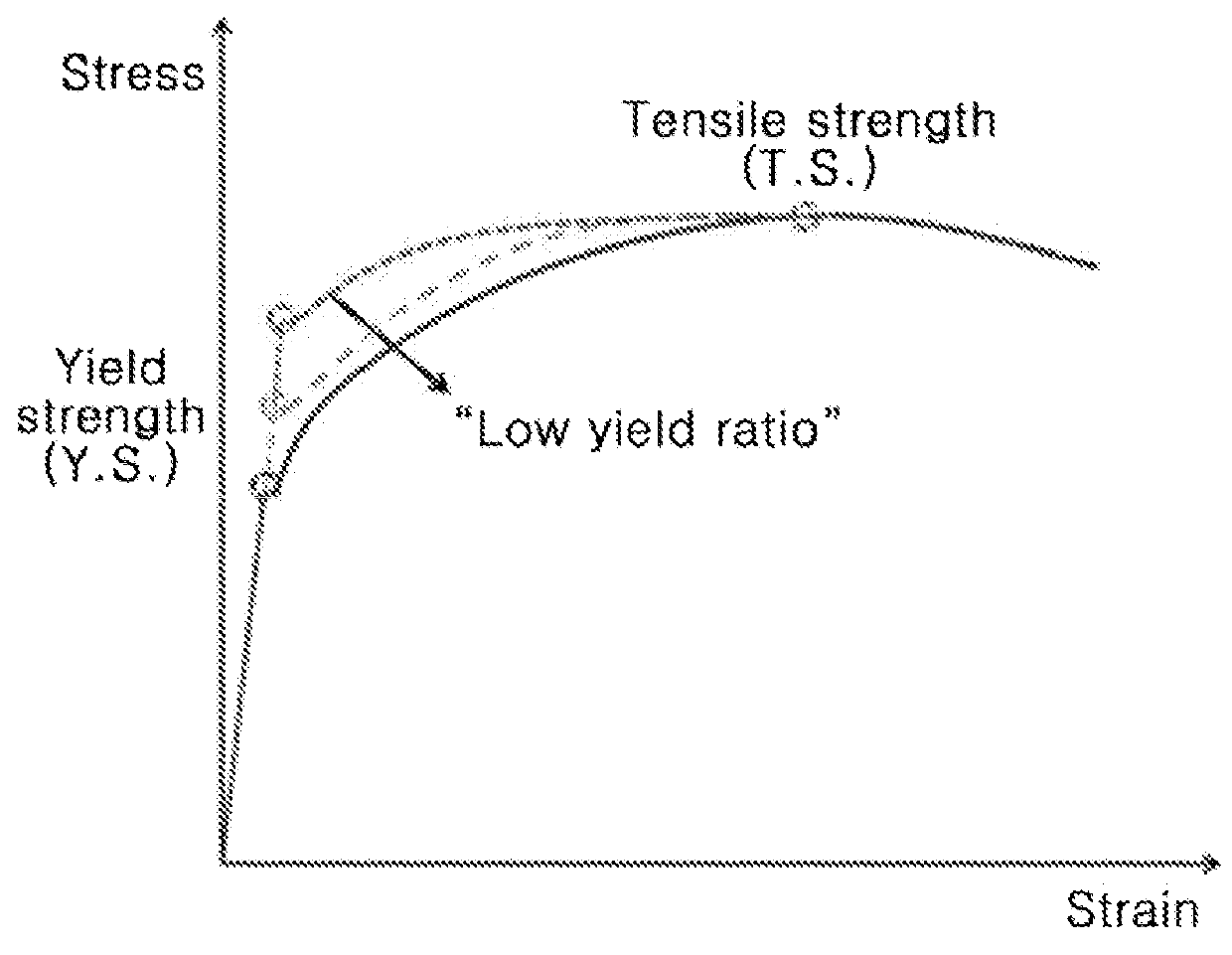
[0073]FIG. 13 is a graph illustrating the stress-strain of the yield ratio-controlled steel YRCS100 of Example 2. As illustrated in FIG. 13, the YRCS100 specimen having a tensile strength of 983 MPa can be confirmed to be usable as a 10T grade high-tension bolt material.

[0074]FIG. 14 illustrates the outer appearances of the bolt (YRCS100 [Forging]) resulting from cold heading of the 10T ...

example 3

Manufacture of Yield Ratio-Controlled Steel (YRCS110) Through Two-Stage Heat Treatment

[0078]In Example 3, a steel wire, comprising 0.30 wt % C, 1.5 wt % Mn, 1.5 wt % Si, and 0.050 wt % Al, with the remainder of Fe and unavoidable impurities, was sequentially subjected to first heat treatment at 800° C. for 35 min, water quenching, and then second heat treatment at 270° C. for 30 min, thus obtaining YRCS110 as yield ratio-controlled steel.

[0079]FIG. 16 is a graph illustrating the stress-strain of the yield ratio-controlled steel YRCS110 of Example 3. As illustrated in FIG. 16, the YRCS110 specimen has a tensile strength of 1167 MPa and can thus be used as an 11T grade high-tension bolt material.


PUM

PropertyMeasurementUnit
tensile strengthaaaaaaaaaa

Abstract

A method of manufacturing yield ratio-controlled steel, including the steps of subjecting alloy steel to rolling or wire drawing, thus obtaining a bar material; performing a first heat treatment, in which the material is heated and maintained for a predetermined period of time at a first temperature ranging from Ac1 to Ac3 based on Ac1 and Ac3 transformation temperatures; and cooling the material to a second temperature ranging from Mf to Ms based on a martensite start temperature (Ms) and a martensite finish temperature (Mf), and performing a second heat treatment, in which the material is maintained at the second temperature for a predetermined period of time.

Description

CROSS-REFERENCE TO RELATED APPLICATION[0001]This application claims priority to Korean Patent Application No. 10-2014-0096321 filed on Jul. 29, 2014 and all the benefits accruing therefrom under 35 U.S.C. §119, the contents of which are incorporated by reference in their entirety.BACKGROUND OF THE INVENTION[0002]1. Field of the Invention[0003]The present invention relates to a steel material and a method of manufacturing the same, wherein the yield ratio of the steel material is controlled, whereby the steel material having the same tensile strength may easily undergo metal working such as plastic working, cutting, etc., and whereby the manufacturing cost thereof may also be decreased.[0004]2. Description of the Related Art[0005]In the manufacture of parts using steel-forged products, many attempts have been made to reduce manufacturing costs through process improvements and automation, among which the elimination of quenching and tempering (which is hereinafter referred to as “Q / T”...

Claims


Application Information

Patent Timeline
Patent Type & Authority Applications(United States)
IPC IPC(8): C21D9/08C21D6/00C21D8/06C22C38/00C22C38/02C22C38/04C22C38/06
CPCC21D9/08C22C38/06C22C38/04C21D8/065C22C38/002C21D6/005C21D6/008C22C38/02
Inventor LEE, YOUNGSEONLEE, CHANG GIL
Owner KOREA INST OF MATERIALS SCI
Why Eureka
Try Eureka