Horseshoe jack for drilling, work-overs and completions

a technology of work-over and completion, which is applied in the direction of drilling rods, drilling pipes, drilling holes/well accessories, etc., can solve the problems of slowed operation, limited prior art examples, and large equipment of the above mentioned, and achieves the effect of reducing the lost rig time, simple control mechanism, and easy power

Active Publication Date: 2016-02-04
1440072 ALBERTA
View PDF1 Cites 4 Cited by
  • Summary
  • Abstract
  • Description
  • Claims
  • Application Information

AI Technical Summary

Benefits of technology

[0010]The extendable and retractable unit employs a simple control mechanism and in one embodiment can be easily powered by tying into a hydraulic pump system with a simple, potentially remote, up / down control (at an operator's control stand) positioned by the driller's console or any convenient location. A separate independent power pack could be available in an alternative embodiment. The motive power can alternatively be by one or more electrically driven rotary motors, using a gear or ball-nut And screw or similar rotary to linear or linear power transmission systems. Other drive systems will be known to those skilled in the art. The rig operator will stroke the Horseshoe Jack unit up or down as necessary while sliding the tubing / casing into position. This operation is very safe and simple and lost rig time will be reduced substantially, by as much as 75% or more. This equipment configuration and procedure can substantially reduce the overall cost on a per well basis.
[0011]Additionally, the unit can be quickly deployed on the rig floor and quickly demounted and removed, even while the tubing extends through its centre, due to its U-shaped mounting plates, merely by demounting the unit's attachment to the well-head or BOP and then removing the unit from around the tubing and then moving it off the rig floor's working area.
[0012]The U-shaped plate or plates of the invention can be provided with a gate, making it possible to surround the tubing with circular plates at intermittent spacing. This may be a useful way to provide rig protection or an anti-bending guide for the tubing to prevent buckling, or to provide extra structural strength to the device.
[0014]A preferred length of the apparatus while compressed is 4′-7′. Although a longer stroke would speed up work over / completion, being able to work with the service rig's floor's limited expandable height is preferred. As for a drilling rig, the same height size allows the end user to keep the stump at a workable height for the crew to make connections. In some cases the unit might be too short. This is easily rectified by adding in a longer hydraulic ram, and spacers / stabilizers and if required, additional plates, to gain height if the unit or its stroke is too short. This option is much better than being of a size which is fixed, but too high / long, which can create an unsafe environment and may not be adjustable. The unit may also be made with a shorter size and stroke, depending on its intended use and deployment (for example, a 10″ stroke may be adequate to dislodge seized or stuck casing dog nuts, hangers or other downhole equipment. There are cases where rig space height is not controllable. A support structure (subfloor, basket) may be added to support a worker at a height above the rig floor. Other benefits of a short, more compact and demountable unit include:
[0016](b) Easier handling with rig up and rig out saves rig time cost;

Problems solved by technology

All of the above mentioned equipment is large and complex equipment to operate, rig up / rig out and service.
Also all the above equipment needs to be manned on a daily basis and suffers from slowed operations and more or less permanent fixturing interfering with rig floor operational spaces.
Additionally, these prior art examples are limited by virtue of their designs to handling tubing with O.D. less than about 7″.
One such piece of equipment that crews have being operating over the last few decades that is much more dangerous to operate is a tubing power swivel.
No rental company presently offers training of the personnel.

Method used


Image

  • Horseshoe jack for drilling, work-overs and completions
  • Horseshoe jack for drilling, work-overs and completions
  • Horseshoe jack for drilling, work-overs and completions

Examples


Embodiment Construction

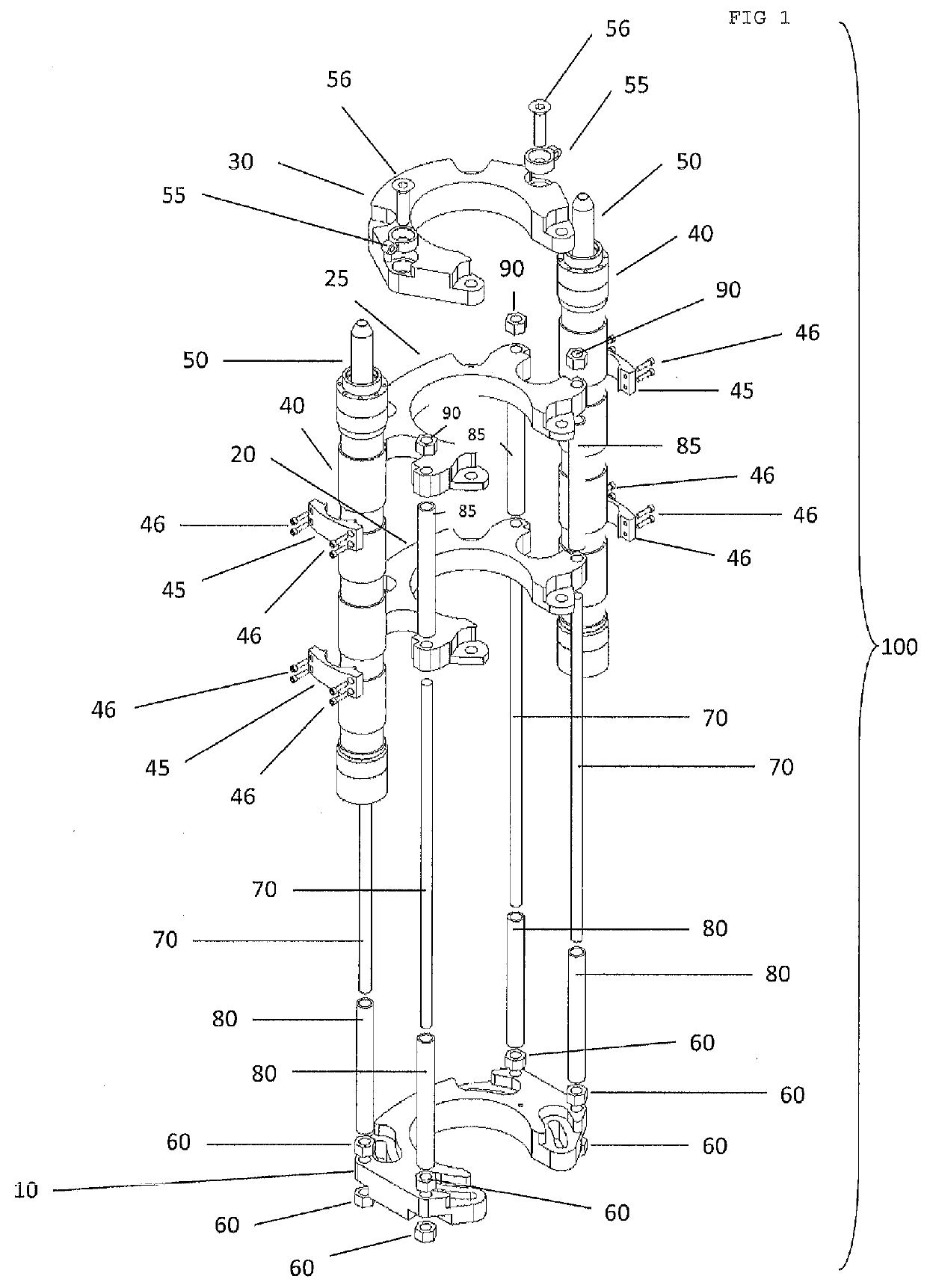
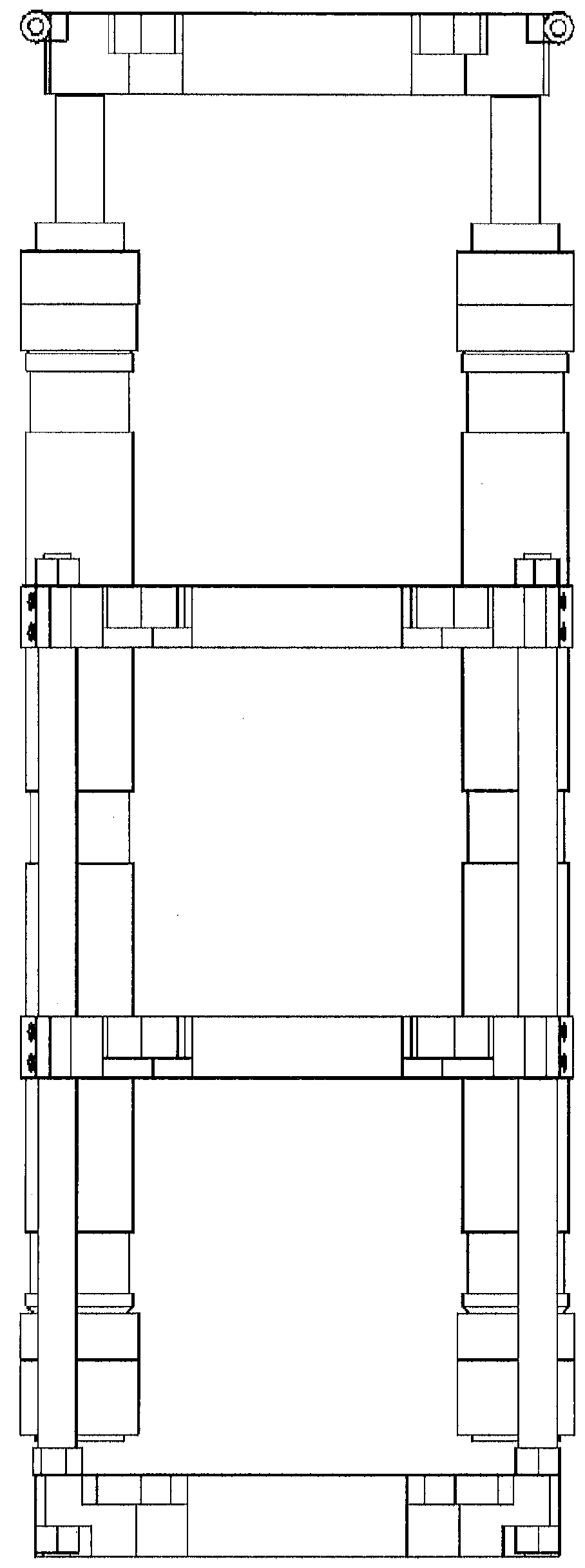
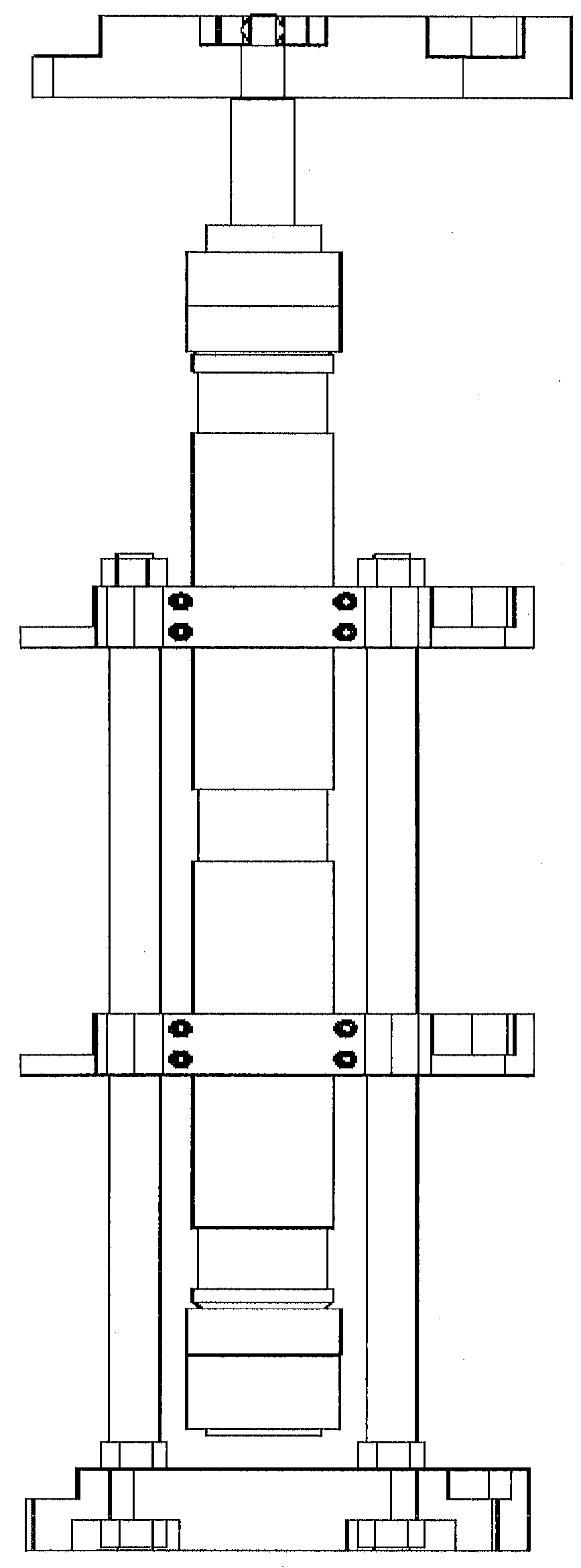
[0028]The following description is of preferred embodiments by way of example only and without limitation to the combination of features necessary for carrying the invention into effect. References is to be had to Figures in which identical reference numbers identify similar components. The drawing figures are not necessarily to scale and certain features are shown in schematic form in the interest of clarity and conciseness.

[0029]A parts list with drawing reference numbers is provided here:

10Lower (interchangeable) Structure Plate20Adjustable Mid-section Structure Plate25Adjustable Mid-section Structure Plate (second)30Travelling Plate, or Top Plate40Hydraulic Ram Cylinder45Ram Cylinder Mounting Bracket46Bolts or Fasteners (removable)50Hydraulic Ram Piston55Ram Unit Lifting Lug56Ram Piston Mounting Bolt60Structural Tie-Rod Nuts / Fasteners (lower)70Structural Tie-Rods80Lower Compression Spacer Tubes85Upper Compression Spacer Tubes90Structural Tie-Rod Nuts / Fasteners (upper)100Horsesho...


PUM


Abstract

A jack and push / pull apparatus is provided by attaching to a wellhead an extendable / contractible horseshoe-shaped jack assembly of sufficient diameter to surround and act upon the tubing or casing to be manipulated in the well, the linear action of the assembly being powered between an extended and a retracted position, the assembly having at least one tube-gripping mechanism at the end of the assembly away from the wellhead attachment. Tubing is inserted into the well bore through the assembly and the wellhead, and when injection forces are desired tube-gripping means grip the tubing being injected and the apparatus is powered to a retracted position, forcing the grasped tubing into the well. The operation may be reversed to pull tubing or casing. The assembly can be simply added to the rig while tubing is present on and above the rig's floor.

Description

FIELD OF THE INVENTION[0001]Horizontal or deviated well operations can require the use of extra force to insert tubing into the well, as compared to forces used in substantially vertical wells, where gravity effects on tubular equipment often provide sufficient impetus. As deviated wells increasingly provide substantially longer non-vertical runs, the need for an ability to supply significantly more force to inject tubing into such wells increases.[0002]In a lot of cases, pressure isolation is not required, and so lubricating fixtures in the prior art are too complex, having superfluous componentry, sealing mechanisms, and the like.BACKGROUND OF THE INVENTION[0003]An example of a system in the prior art includes Funk (U.S. Pat. No. 5,988,274), which describes a tubing lubricator / injector for pressure-sealed snubbing operations. A main goal of the Funk device is to hold wellhead pressure which is significantly higher than atmospheric pressure, and well gases or fluids which may be si...

Claims


Application Information

Patent Timeline
Patent Type & Authority Applications(United States)
IPC IPC(8): E21B19/08
CPCE21B19/08E21B19/086E21B19/06E21B19/07
Inventor PETROWSKY, CONRADFOLLETT, THOMASJOHNSON, BLAKE
Owner 1440072 ALBERTA
Why Eureka
Try Eureka