Methods and controllers for controlling focus of ultraviolet light from a lithographic imaging system, and apparatuses for forming an integrated circuit employing the same

Inactive Publication Date: 2016-02-04
GLOBALFOUNDRIES INC
View PDF3 Cites 10 Cited by
  • Summary
  • Abstract
  • Description
  • Claims
  • Application Information

AI Technical Summary

Benefits of technology

[0007]In another embodiment, an apparatus for forming an integrated circuit includes a lithographic imaging system, a controller, and a measurement device. The lithographic imaging system is configured to pattern a resist film on a wafer through illumination of a lithography mask at an off-normal incidence angle. The controller is programmed to control focus of ultraviolet light produced by the lithographic imaging system. The controller is programmed with instructions to pattern the resist film on the wafer using the ultraviolet light produced by the lithographic imaging system through illumination of the lithography mask at the off-normal incidence angle with a first test pattern formed at a first pitch and a second test pattern formed at a second pitch different from the first pitch, analyze relative shift data obtained from measuring non-telecentricity induced shift of the first test pattern and the second test pattern, and adjust the focus of the ultraviolet light based upon a comparison of the relative shift data to a pre-determined correlation between the non-telecentricity induced shift of the first test p

Problems solved by technology

In lithography techniques that involve extremely small scale of illuminated patterns, such as extreme ultraviolet (EUV) lithography, focus control is often challenging.
However, conventional scatterometry techniques are sensitive to thickness and film properties of the photoresist.
In particular, as the layer thicknesses of the photoresi

Method used


Image

  • Methods and controllers for controlling focus of ultraviolet light from a lithographic imaging system, and apparatuses for forming an integrated circuit employing the same
  • Methods and controllers for controlling focus of ultraviolet light from a lithographic imaging system, and apparatuses for forming an integrated circuit employing the same
  • Methods and controllers for controlling focus of ultraviolet light from a lithographic imaging system, and apparatuses for forming an integrated circuit employing the same

Examples


Embodiment Construction

[0016]The following detailed description is merely exemplary in nature and is not intended to limit the invention or the application and uses of the invention. Furthermore, there is no intention to be bound by any theory presented in the preceding background or the following detailed description.

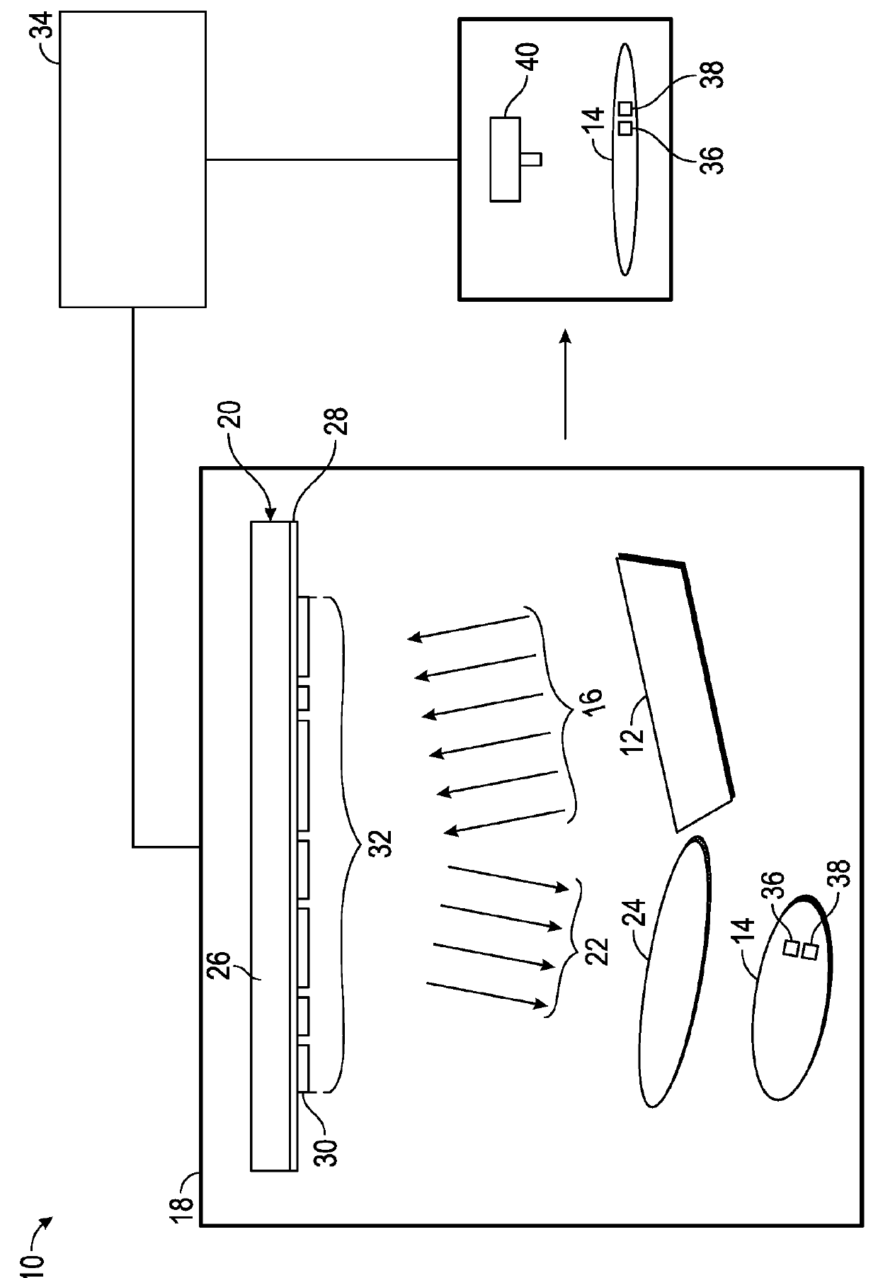
[0017]Methods of controlling focus of ultraviolet (UV) light produced by a lithographic imaging system, apparatuses for forming an integrated circuit employing the method, and controllers programmed to control focus of UV light are provided herein. The methods of monitoring focus of the UV light are particularly suited for lithography techniques that involve extremely small scale of illuminated patterns, such as extreme ultraviolet (EUV) lithography that illuminates a lithography mask at an off-normal incidence angle, and the methods provide adequate sensitivity to changes in focus and are not dependent on a thickness of the photoresist employed during lithography. In particular, non-telecen...


PUM


Abstract

Methods and controllers for controlling focus of ultraviolet light produced by a lithographic imaging system, and apparatuses for forming an integrated circuit employing the same are provided. In an embodiment, a method includes providing a wafer having a resist film disposed thereon. The resist film is patterned through illumination of a lithography mask with ultraviolet light at an off-normal incidence angle with a first test pattern formed at a first pitch and a second test pattern formed at a second pitch different from the first pitch. Non-telecentricity induced shift of the first and second test patterns is measured to produce relative shift data using a measurement device. Focus of the ultraviolet light is adjusted based upon comparison of the relative shift data to a pre-determined correlation between the non-telecentricity induced shift of the first and second test patterns as a function of focus error.

Description

TECHNICAL FIELD [0001]The technical field generally relates to methods of controlling the focus of ultraviolet (UV) light from a lithographic imaging system, apparatuses for forming an integrated circuit that employ the method, and controllers programmed to control the focus of the ultraviolet light. More particularly, the invention relates to methods, apparatuses, and controllers that employ test patterns to adjust the focus of ultraviolet light from the lithographic imaging system.BACKGROUND [0002]Focus control is an important consideration in lithography techniques to ensure proper pattern formation in semiconductor devices. Focus control generally involves focus monitoring to provide feedback for adjusting the focus of UV light from a lithographic imaging system on the semiconductor device. The lithographic imaging system generally includes a light source, a collector (also known as a condenser lens system), a lithography mask (also known as a reticle), and an objective lens (al...

Claims


Application Information

Patent Timeline
IPC IPC(8): G03F7/20
CPCG03F7/70641
Inventor RAGHUNATHAN, SUDHARSHANANWOOD II, OBERT REEVESPREIL, MOSHE E.
Owner GLOBALFOUNDRIES INC
Why Eureka
Try Eureka